Stator assembly method and stator assembly device

An assembly method and a technology for assembling devices, which are applied in the direction of electromechanical devices, windings, electric components, etc., can solve the problems of inability to properly ensure the insulation performance of the slot receiving part and the slot, and the shape of the insulating part is damaged, so as to ensure insulation and prevent The shape is destroyed and the effect of reliable insulation

Active Publication Date: 2020-03-17
AISIN CORP
View PDF8 Cites 1 Cited by
  • Summary
  • Abstract
  • Description
  • Claims
  • Application Information

AI Technical Summary

Problems solved by technology

In addition, it is considered that when the slot housing portion is further moved radially outward in a state where a part of the insulating member is bent and enters the gap, the insulating member (bent portion) mechanically interferes with the slot housing portion and the The insulating member moves radially outward together with the slot housing, so the shape of the insulating member is destroyed
As a result, in the conventional stator assembling method described in the aforementioned U.S. Patent No. 7,788,790 specification, the shape of the insulating member is damaged, and thus the insulating performance between the slot receiving portion and the slot cannot be properly ensured. problems

Method used


Image

  • Stator assembly method and stator assembly device
  • Stator assembly method and stator assembly device
  • Stator assembly method and stator assembly device

Examples


Embodiment Construction

[0035] Hereinafter, embodiments of the present invention will be described with reference to the drawings.

[0036] [Structure of the stator]

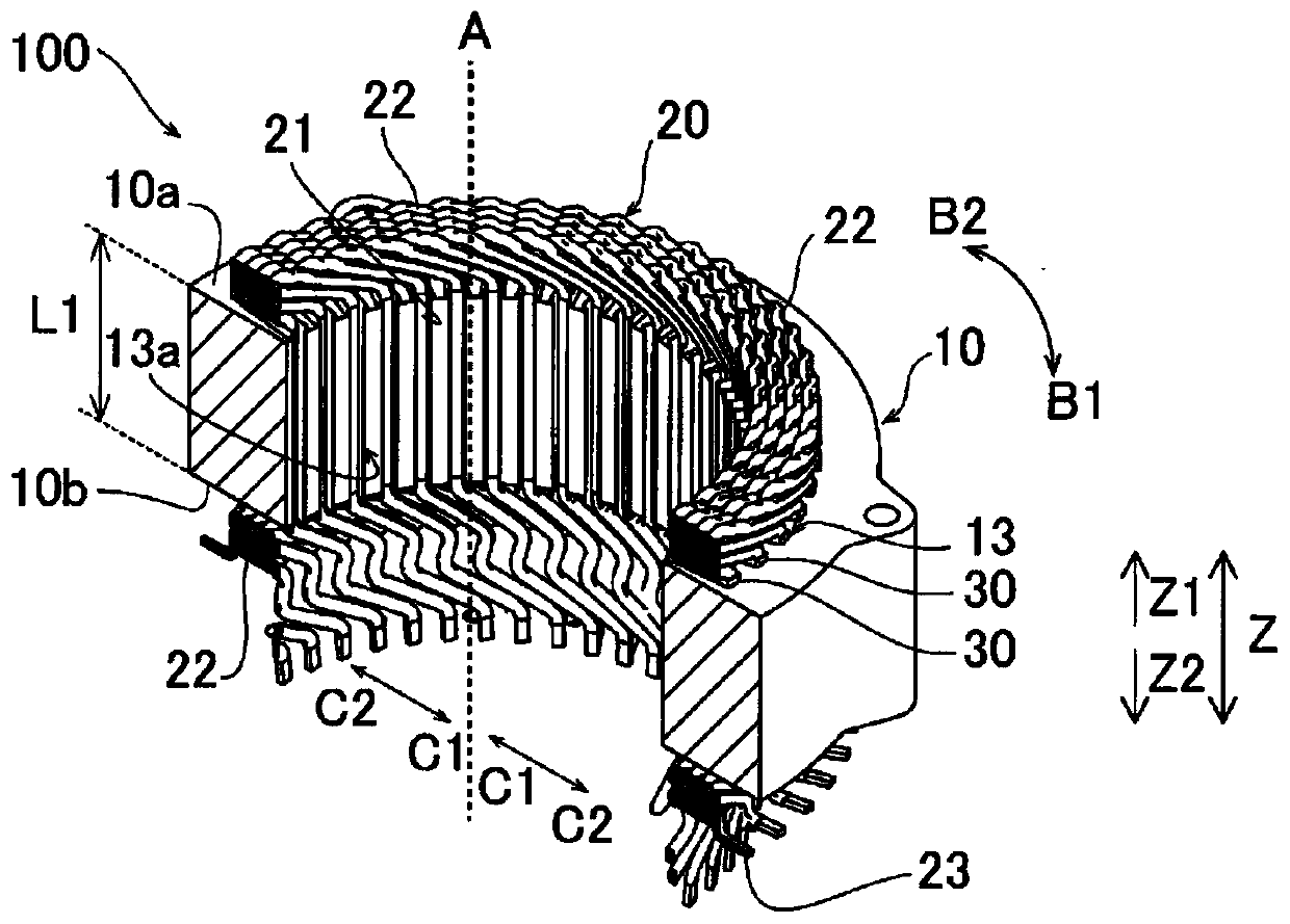
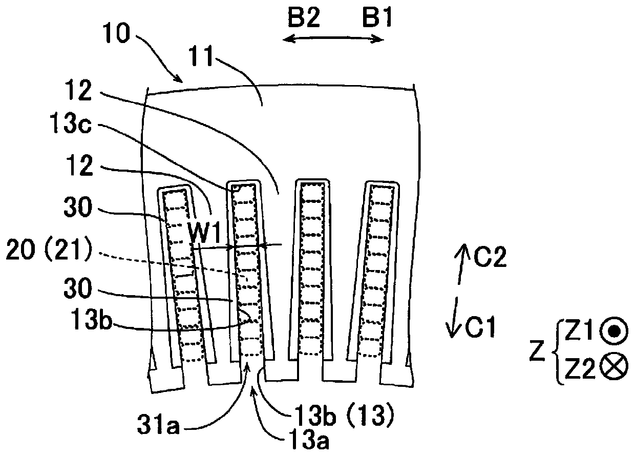
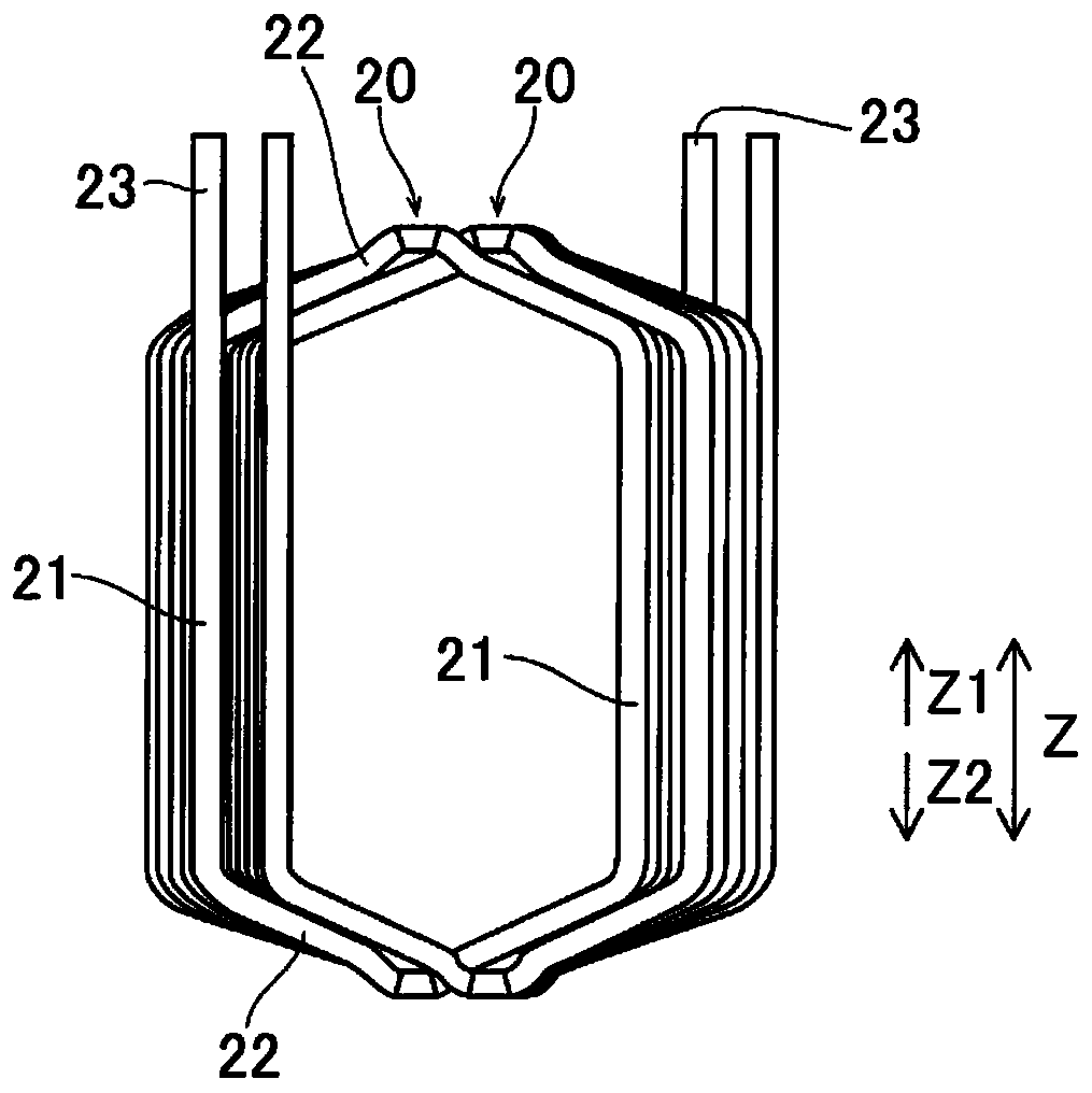
[0037] Reference Figure 1 ~ Figure 4 The structure of the stator 100 of this embodiment is demonstrated. In addition, in figure 1 Although the oblique cross-sectional view (semi-circular shape) of the stator 100 is shown, the stator 100 is formed in a circular ring shape.

[0038] In addition, in the specification of this application, "central axis direction" and "axial direction" mean along figure 1 The direction (Z direction) of the central axis A (rotation axis of the rotor) of the stator core 10 (stator 100) shown. In addition, the "circumferential direction" is the circumferential direction (the B1 direction or the B2 direction) of the designated sub-core 10. In addition, the “radial direction” refers to the radial direction of the designated sub-core 10. In addition, "radially inner side" refers to the direction (C1 direction) towar...


PUM


Abstract

A stator assembly method comprising: a step in which a first guide jig is inserted into an insulating member arranged in a slot along a center axis direction, and a portion of the insulating member onradially one side is opened; and a step in which a coil and the first guide jig are together moved toward the radially other side with respect to the stator core, thereby inserting a slot accommodation part into the slot via an opening.

Description

Technical field [0001] The present invention relates to a method for assembling a stator and an assembling device for the stator, and in particular to a stator having a process of moving a coil in the radial direction of the stator core, thereby inserting the slot accommodating portion of the coil into the slot of the stator core Assembly method and stator assembly device. Background technique [0002] Conventionally, there has been known a stator assembling method including a process of moving the coil in the radial direction of the stator core to insert the slot housing portion of the coil into the slot of the stator core. The assembly method of such a stator is disclosed in, for example, the specification of US Patent No. 7,788,790. [0003] In the stator assembly method described in the specification of US Patent No. 7,788,790, after arranging the insulating member in the core slot of the stator core (hereinafter referred to as "slot"), the clamp is arranged inside the insulat...

Claims


Application Information

Patent Timeline
Patent Type & Authority Applications(China)
IPC IPC(8): H02K15/085H02K15/10
CPCH02K15/085H02K1/16H02K15/066H02K3/345H02K15/10
Inventor 井出光洋铃木大将
Owner AISIN CORP
Why Eureka
Try Eureka