
Display panel

A technology for display panels and substrates, which is applied in static indicators, nonlinear optics, instruments, etc., and can solve the problems of low transmittance of display panels and obvious dark stripes.

Active Publication Date: 2020-03-17
SHENZHEN CHINA STAR OPTOELECTRONICS SEMICON DISPLAY TECH CO LTD
View PDF6 Cites 1 Cited by
  • Summary
  • Abstract
  • Description
  • Claims
  • Application Information

AI Technical Summary

Problems solved by technology

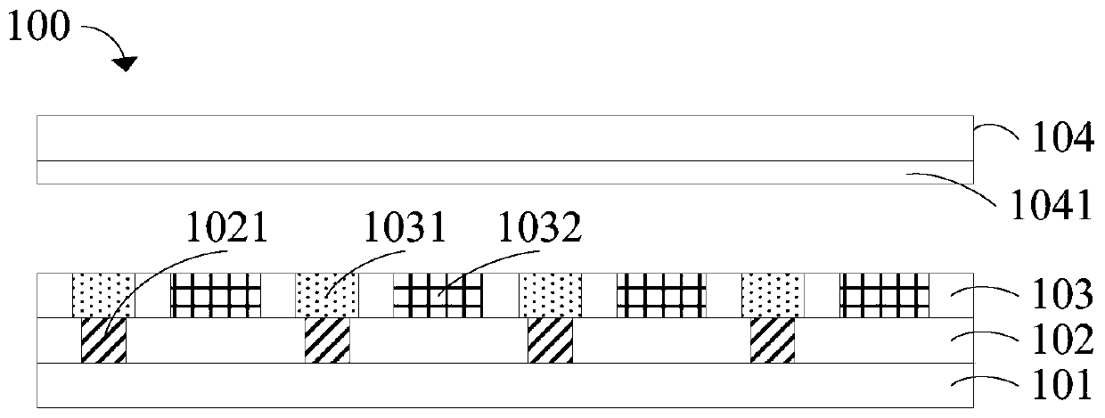
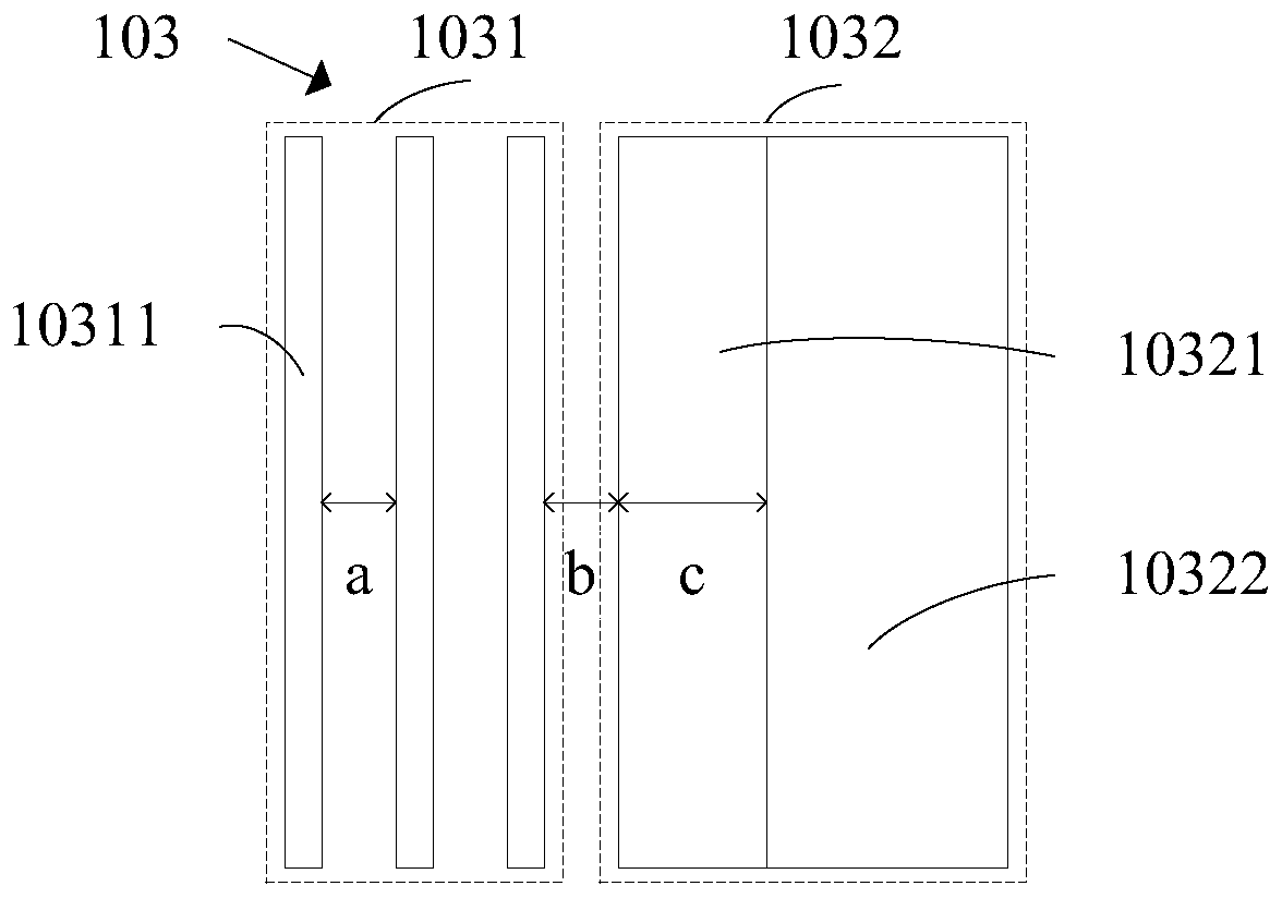
[0005] The object of the present invention is to provide a display panel. By setting the shielding electrode to include a plurality of sub-shading electrodes, and the plurality of sub-shading electrodes are arranged in parallel with the data lines, the existing darkening between the shielding electrode and the pixel electrode is solved. The stripes are more obvious, which leads to the problem of low transmittance of the display panel

Method used


Image

  • Display panel
  • Display panel
  • Display panel

Examples


Embodiment Construction

[0032] The technical solutions in the embodiments of the present invention will be clearly and completely described below in conjunction with the drawings in the embodiments of the present invention. Apparently, the described embodiments are only some of the embodiments of the present invention, but not all of them. Based on the embodiments of the present invention, all other embodiments obtained by those skilled in the art without creative efforts fall within the protection scope of the present invention.

[0033] In the description of the present invention, it should be understood that the orientation or positional relationship indicated by the terms "upper", "lower", "near" and the like are based on the orientation or positional relationship shown in the drawings, wherein "upper" is just a superficial Above the object, specifically refers to directly above, obliquely above, or on the upper surface, as long as it is above the level of the object. "Close" refers to two object...


PUM

PropertyMeasurementUnit
widthaaaaaaaaaa

Abstract

The invention provides a display panel comprising a substrate, a circuit layer arranged on the substrate, and a pixel layer arranged on the circuit layer. The circuit layer includes a plurality of data lines that are arranged in parallel. The pixel layer includes a plurality of shielding electrodes and a plurality of pixel electrodes; the shielding electrodes are opposite to the data lines; the pixel electrodes are arranged between the adjacent shielding electrodes; each shielding electrode includes a plurality of sub-shielding electrodes that are parallel to the data lines. Therefore, dark stripes between the shielding electrodes and the pixel electrodes can be reduced, and the penetration rate of the display panel can be increased.

Description

technical field [0001] The present invention relates to the field of display technology, in particular to the manufacture of display devices, in particular to a display panel. Background technique [0002] At present, when making a display panel, in order to increase the aperture ratio of the panel, an ITO (Indium tin oxide, indium tin oxide) material will be arranged above the data line, that is, the ITO material will be arranged between adjacent pixel electrodes. When the display panel is in operation, the liquid crystal molecules on the ITO material are not deflected to achieve a light-shielding effect, replacing the BM (Black Matrix) originally arranged on the color filter substrate 104 . [0003] However, when performing picture display, the deflection direction of the liquid crystal above the area between the ITO material and the adjacent pixel electrode is not ideal, resulting in a phenomenon between the ITO material and the area between the adjacent pixel electrode. ...

Claims


Application Information

Patent Timeline
Patent Type & Authority Applications(China)
IPC IPC(8): G02F1/1343G02F1/133
CPCG02F1/134309G02F1/13306G02F1/134345G02F1/136218G02F1/136286G02F1/1368
Inventor 张琪曹武
Owner SHENZHEN CHINA STAR OPTOELECTRONICS SEMICON DISPLAY TECH CO LTD
Learn More