
Wire drawing machine controller system

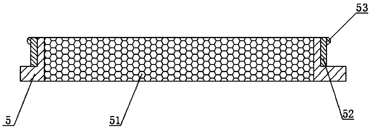
A technology for controllers and wire drawing machines, applied in the field of wire drawing machines, can solve the problems of inconvenient cleaning of the mesh of the filter plate, reduce the heat dissipation effect of the installation shell, and inconvenient disassembly and assembly of the filter plate, so as to improve maintenance efficiency and facilitate cleaning , The effect of convenient switching

Inactive Publication Date: 2020-03-17
瑞安市通源自动化设备有限公司
View PDF7 Cites 3 Cited by
  • Summary
  • Abstract
  • Description
  • Claims
  • Application Information

AI Technical Summary

Problems solved by technology

[0003] At present, in the wire drawing machine, especially the control part of the straight-in wire drawing machine, most of them adopt the mode of "programmable logic controller (PLC)" + "frequency converter", but the installation shell set by the existing wire drawing machine controller system When installing the components of the controller system, since the installation plate is fixed in the housing, the installation position is limited, which not only affects the installation efficiency, but also makes the small space difficult for later maintenance, and most of the filter panels installed in the installation housing It is not easy to disassemble and assemble, so it is not convenient to clean the mesh holes set on the filter screen. After a long time of use, the mesh holes may be blocked by dust and debris, thereby reducing the heat dissipation effect of the installation shell

Method used


Image

  • Wire drawing machine controller system
  • Wire drawing machine controller system
  • Wire drawing machine controller system

Examples


Embodiment Construction

[0026] The technical solutions in the embodiments of the present invention will be clearly and completely described below in conjunction with the accompanying drawings in the embodiments of the present invention. Obviously, the described embodiments are only a part of the embodiments of the present invention, rather than all the embodiments. Based on the embodiments of the present invention, all other embodiments obtained by those of ordinary skill in the art without creative work shall fall within the protection scope of the present invention.

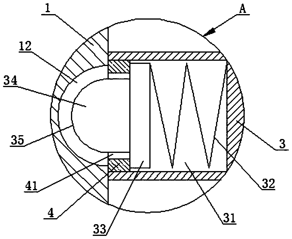
[0027] See Figure 1-3 , A wire drawing machine controller system, including housing 1, please refer to Figure 1-3 , The upper left side of the housing 1 is hinged with the upper cover 2 through the hinge, the upper end of the housing 1 is provided with a storage slot 11, the storage slot 11 is used to receive the mounting board 3 and the controller system inverter and fixed installation on the mounting board 3 The PLC and other compon...


PUM


Abstract

The invention discloses a wire drawing machine controller system, and belongs to the technical field of wire drawing machines. The wire drawing machine controller system is characterized in that an upper cover is hinged to the left side of the upper end of a shell through a hinge; a storage groove is arranged in the upper end of the shell; adjusting holes are arranged in the inner wall of the sideface of the storage groove; the adjusting holes are vertically distributed at an equal interval; a mounting plate is slidably connected in the storage groove; symmetrical grooves are arranged in thetwo ends of the mounting plate; a spring is connected in each groove in a contact manner; a limiting block is connected to the left end of each spring in a contact manner; a chuck is fixedly connectedto the left side of each limiting block; an arranged filter plate is provided with a quick sealing installation and disassembly function, a user can conveniently clean a filter screen, the influenceof the blockage of a mesh of the filter screen on the heat dissipation effect is prevented, and the convenience for use of the filter plate is improved; and furthermore, the arranged mounting plate has the functions of vertical movement and automatic positioning, when the user overhauls the controller system, the mounting plate can be moved upwards to increase the working space, and the overhaul efficiency is improved.

Description

Technical field [0001] The invention relates to the technical field of wire drawing machines, and more specifically, to a wire drawing machine controller system. Background technique [0002] Wire drawing machines are also called wire drawing machines and wire drawing machines. They are widely used in industrial applications. They are widely used in machinery manufacturing, hardware processing, petrochemicals, plastics, bamboo and wood products, wires and cables. [0003] At present, the control part of the wire drawing machine, especially the straight wire drawing machine, mostly adopts the "programmable controller (PLC)" + "inverter" mode, but the existing wire drawing machine controller system is set in the installation shell When installing the controller system components, because the mounting plate is fixed in the shell, the installation position is limited, which not only affects the installation efficiency, but also the small space is not convenient for later maintenance, a...

Claims


Application Information

Patent Timeline
IPC IPC(8): B21C1/02
CPCB21C1/02
Inventor 柯王宣王祖格
Owner 瑞安市通源自动化设备有限公司
Learn More