
Visual memory chip repair analysis program inspection method and device

A technology of memory chips and programs, applied in CAD circuit design, etc., can solve the problems of cumbersome process and time-consuming, and achieve the effect of saving time

Active Publication Date: 2020-03-13
CHANGXIN MEMORY TECH INC
View PDF6 Cites 6 Cited by
  • Summary
  • Abstract
  • Description
  • Claims
  • Application Information

AI Technical Summary

Problems solved by technology

[0004] However, in the existing test program verification methods, the process of obtaining malfunctioning test results is very abstract. At the same time, manual observation is required to repair the calculation method or replace the rules, which is cumbersome and time-consuming.

Method used


Image

  • Visual memory chip repair analysis program inspection method and device
  • Visual memory chip repair analysis program inspection method and device
  • Visual memory chip repair analysis program inspection method and device

Examples


Embodiment 1

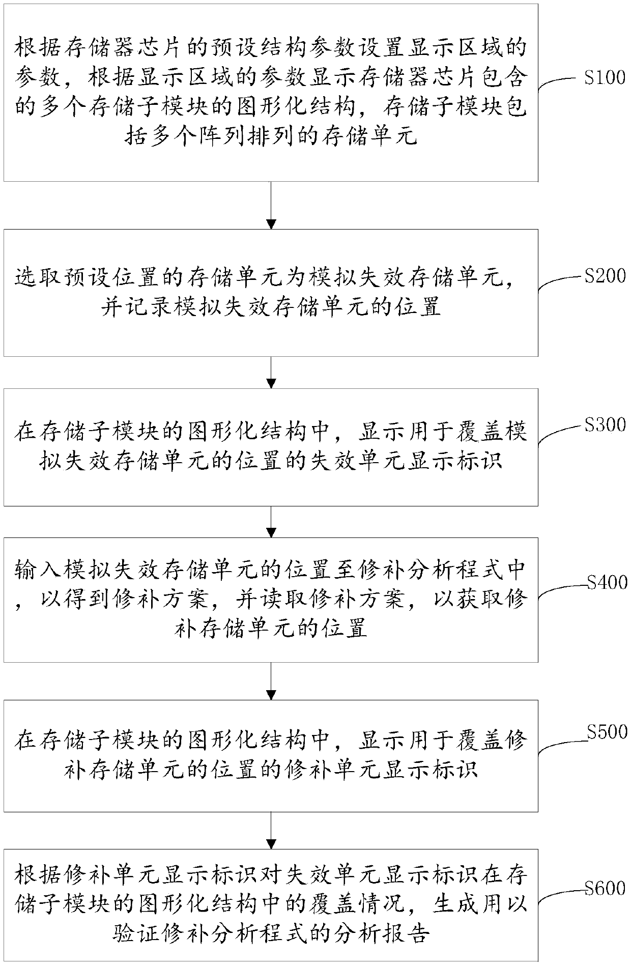
[0075] In a specific embodiment, a visual memory chip repair analysis program verification method is provided, such as figure 1 and image 3 shown, including the following steps:

[0076] Step S100: Set the parameters of the display area according to the preset structural parameters of the memory chip 10, and display the graphical structure 200 of the multiple storage sub-modules contained in the memory chip 10 according to the parameters of the display area. storage unit 210 .

[0077] Such as figure 2 As shown, the memory chip 10 includes a plurality of storage sub-modules 11, and the number of the storage sub-modules 11 can generally be determined according to the total capacity of the memory chip. Each storage sub-module 11 includes a plurality of data bits 12 with a storage array. The memory array is composed of memory cells 210 .

[0078] Such as figure 2 As shown, the preset structural parameters of the memory chip 10 include the total number of memory sub-modul...

Embodiment 2

[0112] The present invention also provides a visual memory chip repair analysis program checking device, such as Figure 8 shown, including:

[0113] The graphical structure setting module 10 is used to set the parameters of the display area according to the preset structural parameters of the memory chip, and display the graphical structure 200 of a plurality of storage sub-modules 11 contained in the memory chip according to the parameters of the display area. The storage sub-module 11 includes A plurality of storage units 210 arranged in an array;

[0114] The simulated failure storage unit setting module 20 is used to select the storage unit 210 of the preset position as the simulated failure storage unit 220, and record the position of the simulated failure storage unit 220;

[0115] The failure unit display mark 230 display module 30 is used to display the failure unit display mark 230 for covering the position of the simulated failure storage unit 220 in the graphical...


PUM


Abstract

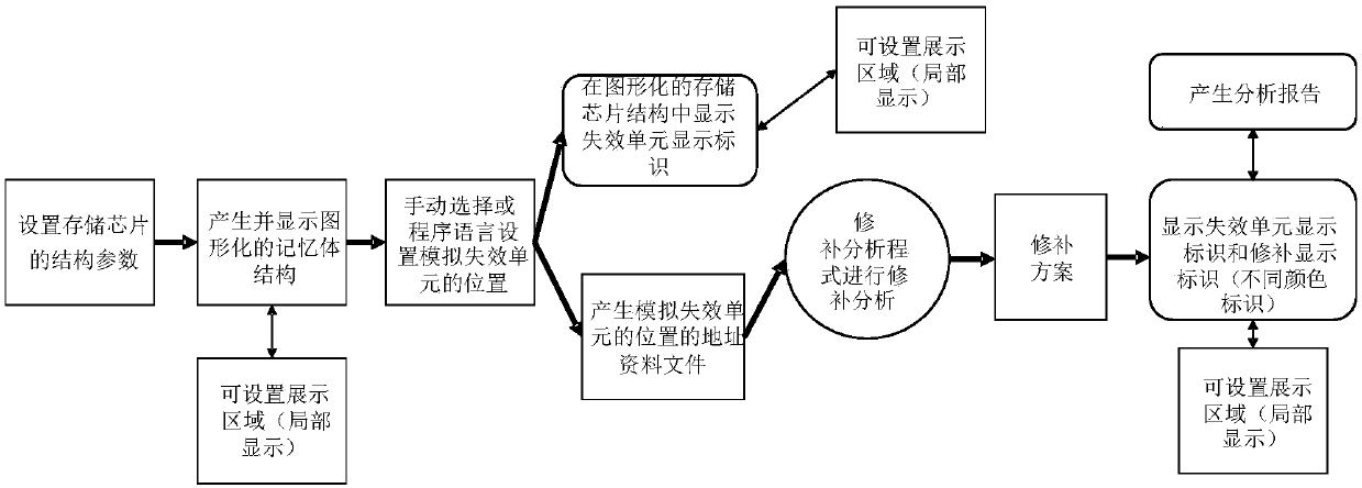
The invention provides a visual memory chip repair analysis program inspection method and a device, and the method comprises the steps: displaying a graphical structure of a plurality of storage sub-modules contained in a memory chip according to the parameters of a display region, and each storage sub-module comprises a plurality of storage units arranged in an array; selecting a storage unit ata preset position as a simulation failure storage unit, and recording the position of the simulation failure storage unit; displaying a failure unit display identifier for covering the position of thesimulation failure storage unit; inputting the position of the simulation failure storage unit into the repair analysis program to obtain a repair scheme so as to obtain the position of the repair storage unit; displaying a repair unit display identifier for covering the position of the repair storage unit; and generating an analysis report according to the coverage condition of the repair unit display identifier on the failure unit display identifier. The whole process and the inspection result of the inspection and repair analysis program are visually and vividly displayed, convenience andquickness are achieved, and time is saved.

Description

technical field [0001] The invention relates to the technical field of semiconductor integrated circuits, in particular to a visual memory chip repair analysis program inspection method, and also relates to a visual memory chip repair analysis program inspection device. Background technique [0002] Memory circuits are an important part of semiconductor integrated circuits. With the increasing storage capacity of memories, memory testing has become a key content in semiconductor integrated circuits. How to effectively test memory circuits is a problem that those skilled in the art are more and more concerned about. [0003] The functional test in the memory is composed of input vector and output response, and checks whether the internal structure of the chip realizes the correct operation required by the design scheme. Its content includes testing whether all memory cells can be read, written and maintained data. At present, technicians conduct various types of functional ...

Claims


Application Information

Patent Timeline
Patent Type & Authority Applications(China)
IPC IPC(8): G06F30/36
Inventor 汪锡
Owner CHANGXIN MEMORY TECH INC
Learn More