Energy storage heat exchange device and air conditioning equipment

A heat exchange device and energy storage technology, which is applied in the field of air conditioning, can solve the problems of continuous cooling of air conditioning equipment, the inability of energy storage materials to absorb heat infinitely, and poor user experience, so as to improve battery life, simple structure, and user experience. Good results

Inactive Publication Date: 2020-03-13
GUANGDONG MIDEA WHITE HOME APPLIANCE TECH INNOVATION CENT CO LTD +1
View PDF8 Cites 1 Cited by
  • Summary
  • Abstract
  • Description
  • Claims
  • Application Information

AI Technical Summary

Problems solved by technology

[0002] The prior art proposes a scheme of using a heat exchanger to exchange heat with an energy storage material for condensation in air-conditioning equipment. Specifically, the heat exchanger is immersed in the energy storage material in the container, so that the heat exchanger condenses toward the energy storage material. Condensation by releasing heat. However, the energy storage material cannot absorb heat infinitely. After a period of cooling operation, the air conditioner needs to regenerate the energy storage material. To meet this demand, the existing technology proposes that the air conditioner switch the flow path so that the heat exchanger The solution is to absorb heat from the energy storage material to regenerate it, but in this solution, the heat exchanger cannot cool at the same time during the process of absorbing heat from the energy storage material to regenerate it, that is, the air conditioner cannot continue to cool, and the product experience is not good

Method used


Image

  • Energy storage heat exchange device and air conditioning equipment
  • Energy storage heat exchange device and air conditioning equipment
  • Energy storage heat exchange device and air conditioning equipment

Examples


specific Embodiment 1

[0059] Specific embodiment one (as Figure 1 to Figure 10 shown)

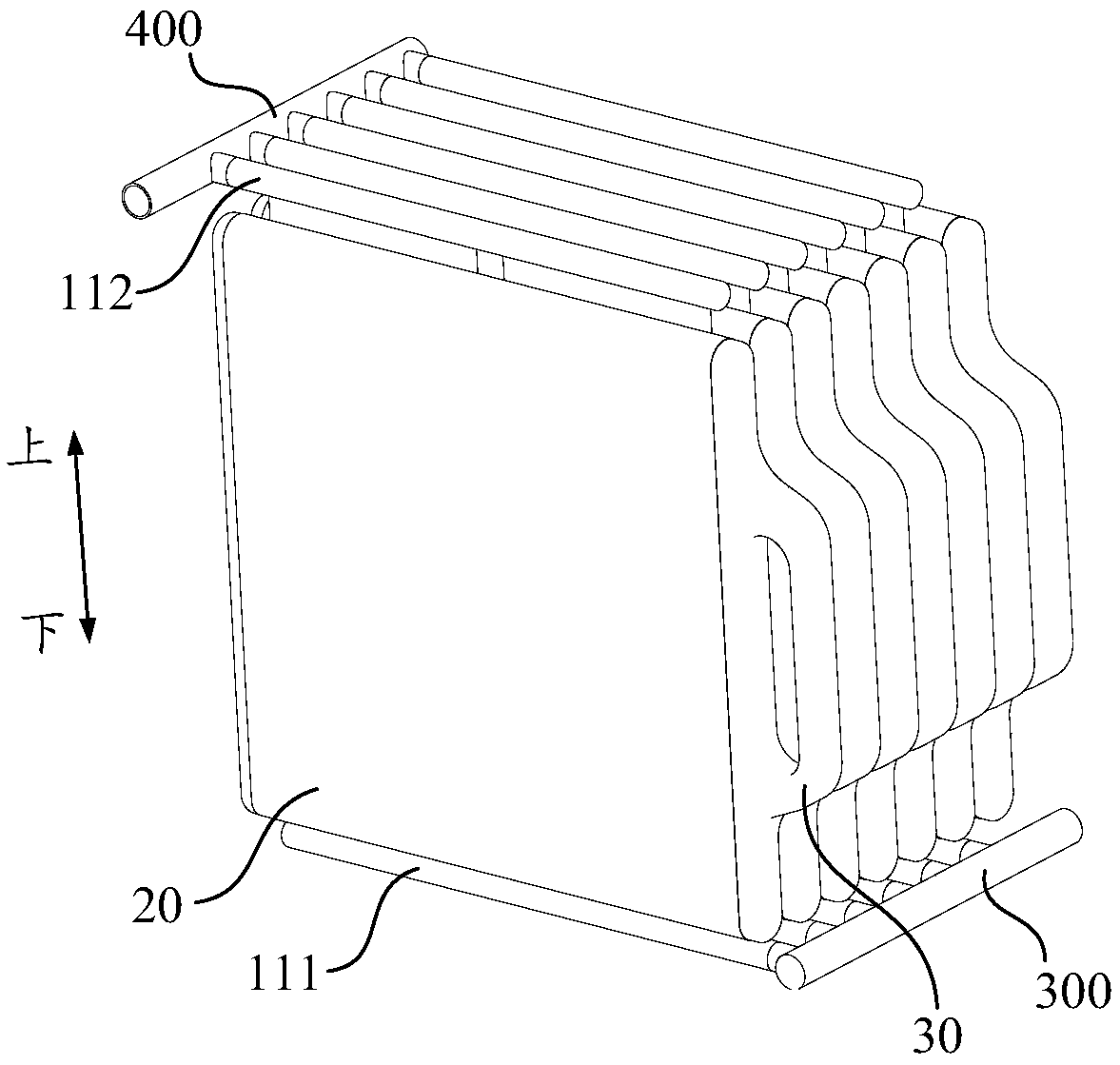
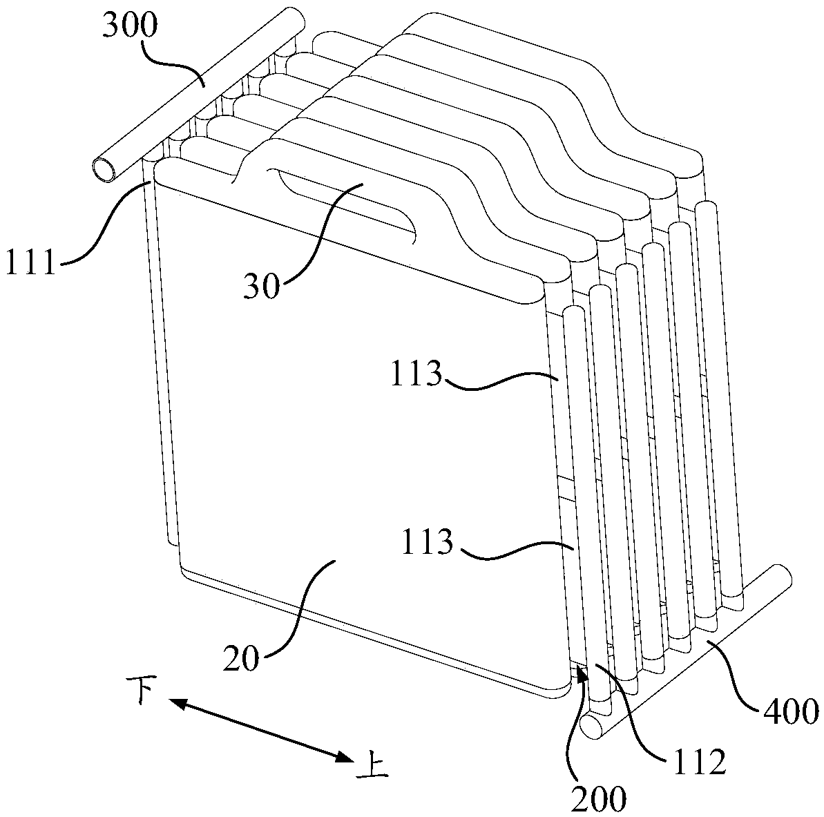
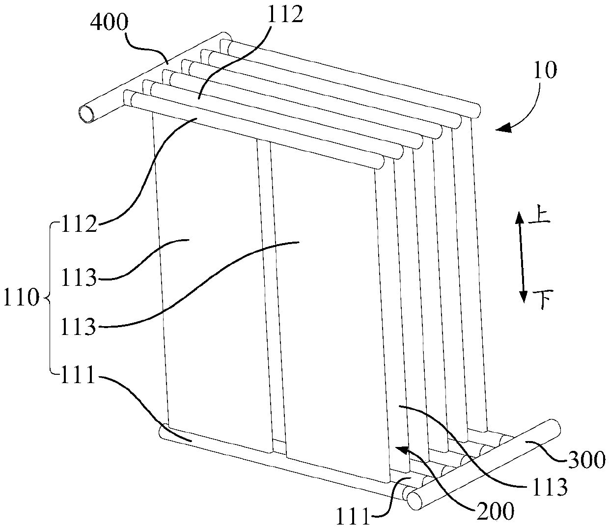
[0060] like Figure 1 to Figure 4 As shown, the heat exchanger 10 further includes a liquid collection pipe 300 and a liquid distribution pipe 400 , and each heat exchanger unit 100 is connected with the liquid collection pipe 300 and the liquid distribution pipe 400 .

[0061] Wherein, in the energy storage heat exchange device of this design, the heat exchanger 10 can be used as an ice storage heat exchanger, and can also be used as a cold conduction heat exchanger.

[0062] When used as an ice storage heat exchanger, the entire heat exchanger 10 acts as an evaporator, and the low-temperature refrigerant enters the heat exchanger unit 100 from the liquid header 300, and transfers the cooling capacity by heat conduction during the process of passing through the heat exchanger unit 100. Transfer to the energy storage element 20 , the energy storage material water in the energy storage element 20 is made into ...

specific Embodiment 2

[0069] Specific embodiment two (as Figure 11 shown)

[0070] The difference from the previous specific embodiment 1 is that the heat exchanger unit 100 includes a refrigerant pipe 121 and a heat conduction plate 122, and the microchannel flat tube 113 in the specific embodiment 1 is replaced with a component including the refrigerant pipe 121 and the heat conduction plate 122, Specifically, the refrigerant pipe 121 communicates with the liquid collection pipe 300 and the liquid distribution pipe 400; the heat conduction plates 122 of adjacent heat exchanger units 100 face each other, so that slots 200 are formed between the heat conduction plates 122 of adjacent heat exchanger units 100, The refrigerant pipe 121 is connected to the heat conduction plate 122 , and when the energy storage element 20 is plugged into the slot 200 , the heat conduction plate 122 conducts heat between the refrigerant pipe 121 and the energy storage element 20 . Among them, the use of the heat cond...

specific Embodiment 3

[0077] Specific embodiment three (as Figure 12 shown)

[0078] The difference from the first specific embodiment above is that the heat exchanger unit 100 includes several plates 131, which are stacked and arranged, and the adjacent plates 131 are sealed and connected to form a refrigerant flow channel 133, for example, The heat exchanger unit 100 includes two plates 131 to form a single refrigerant channel 133, or the heat exchanger unit 100 includes three plates 131 to form a double refrigerant channel 133, and the heat exchanger unit 100 includes four plates 131 Form three refrigerant channels 133 and so on, wherein each refrigerant channel 133 has a first opening 134 and a second opening 135, the first opening 134 communicates with the liquid collecting pipe 300, and the second opening 135 communicates with the liquid pipe 400, The surface plates 131 between adjacent heat exchanger units 100 are arranged oppositely, so that the slots 200 are formed between the surface pl...


PUM


Abstract

The invention provides an energy storage heat exchange device and air conditioning equipment. The energy storage heat exchange device comprises: a heat exchanger which comprises a plurality of heat exchanger units, wherein the heat exchanger units are distributed at intervals, and an inserting groove is formed between the adjacent heat exchanger units; and an energy storage piece which is internally provided with an energy storage material, wherein the energy storage piece can be inserted into the inserting groove and can be detached from the inserting groove, and the energy storage piece canmake contact with the heat exchanger units on the two sides of the inserting groove and exchange heat when inserted into the inserting groove. According to the energy storage heat exchange device provided by the scheme, the energy storage piece and the heat exchanger can be conveniently assembled and disassembled, intermittent refrigeration of the air conditioning equipment can be achieved throughcold storage regeneration-refrigeration cycle circulation, and continuous refrigeration can be achieved in a mode of replacing the energy storage piece in time.

Description

technical field [0001] The invention relates to the field of air conditioners, in particular to an energy storage heat exchange device and an air conditioner. Background technique [0002] The prior art proposes a scheme of using a heat exchanger to exchange heat with an energy storage material for condensation in air-conditioning equipment. Specifically, the heat exchanger is immersed in the energy storage material in the container, so that the heat exchanger condenses toward the energy storage material. Condensation by releasing heat. However, the energy storage material cannot absorb heat infinitely. After a period of cooling operation, the air conditioner needs to regenerate the energy storage material. To meet this demand, the existing technology proposes that the air conditioner switch the flow path so that the heat exchanger The solution is to absorb heat from the energy storage material to regenerate it, but in this solution, the heat exchanger cannot cool at the sam...

Claims


Application Information

Patent Timeline
Patent Type & Authority Applications(China)
IPC IPC(8): F28D20/02F28F1/02F28F1/10F28F9/02F28F11/02F28F21/08F24F5/00
CPCF24F5/0021F28D20/021F28F1/022F28F1/10F28F9/02F28F11/02F28F21/08F28F2260/02F28F2275/04Y02E60/14
Inventor 刘和成林晨岳宝大森宏
Owner GUANGDONG MIDEA WHITE HOME APPLIANCE TECH INNOVATION CENT CO LTD
Why Eureka
Try Eureka