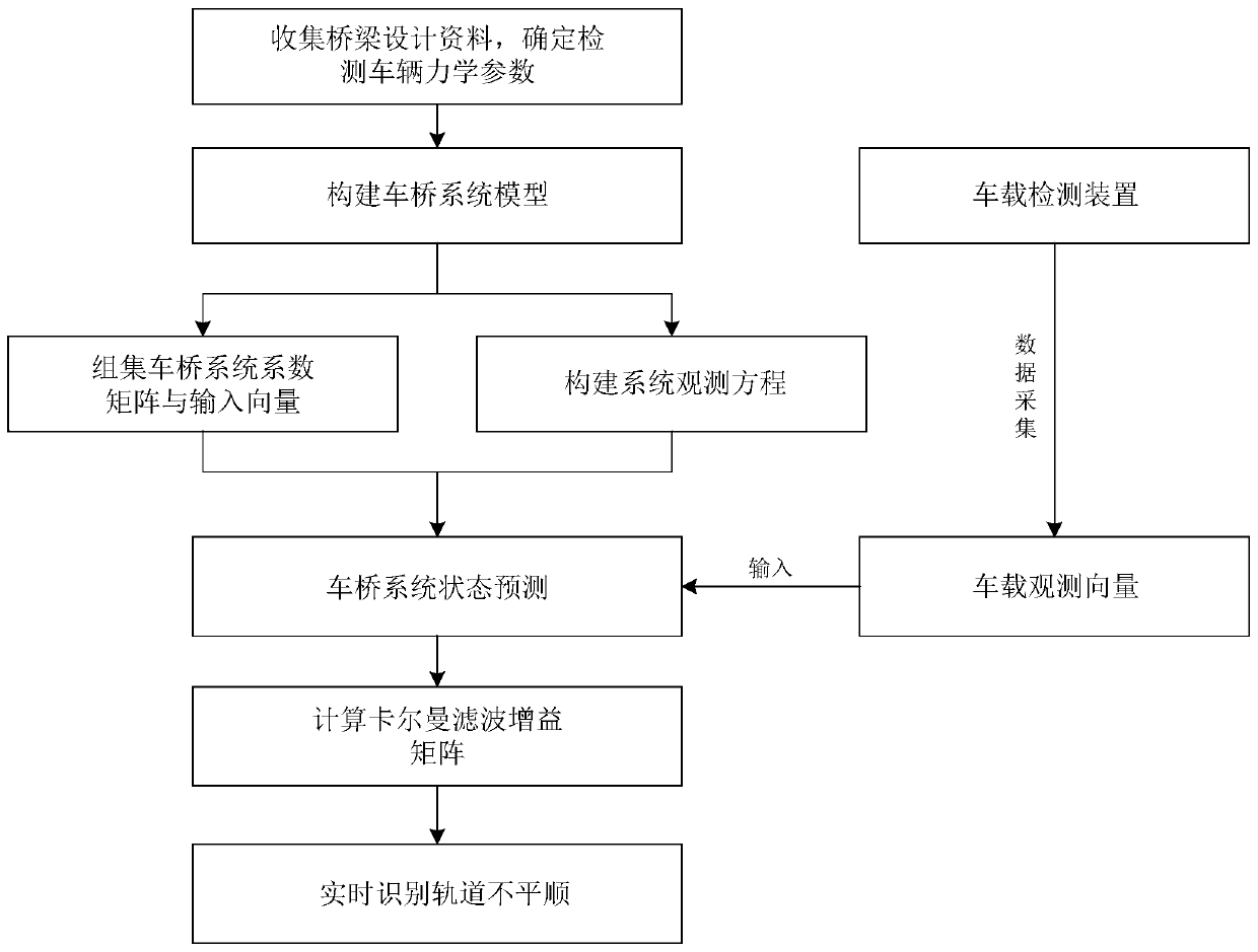
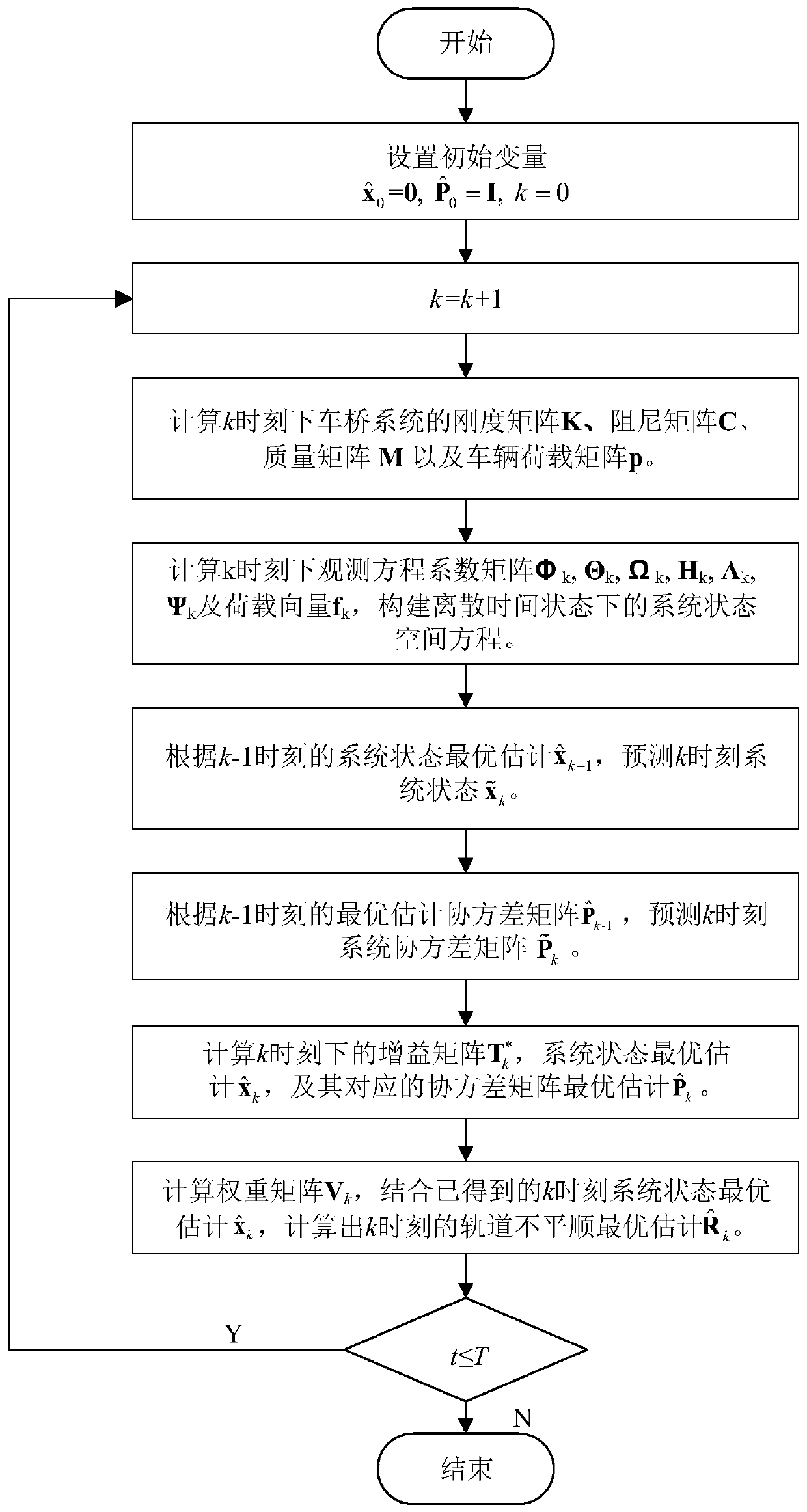
Railway bridge track irregularity calculation method based on vehicle-mounted monitoring
A track irregularity and calculation method technology, which is applied in the field of track irregularity calculation of railway bridges based on vehicle monitoring, can solve the problems of difficulty in meeting the engineering needs of track smoothness detection, large numerical errors, etc.
- Summary
- Abstract
- Description
- Claims
- Application Information
AI Technical Summary
Problems solved by technology
Method used
Image
Examples
Embodiment 1
[0121] Example 1: Figure 4 Shown is a schematic diagram of a railway girder bridge on the Hangzhou-Changsha high-speed railway section. The bridge is a double-span simply supported prestressed bridge, and the length of each simply supported beam is L=32m. The main girder adopts Figure 5 Box-section structure shown, mass per unit length m b =9.4×10 3 kg / m, bridge elastic modulus E=3.45×10 10 N / m 2 , section moment of inertia I = 3.2m 4 .
[0122] Identification steps:
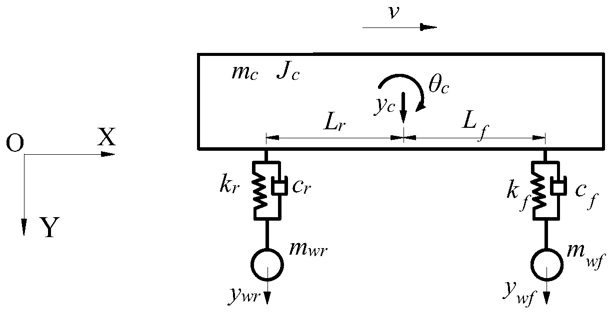
[0123] Step 1: Select the vehicle for detection, and the parameters of the vehicle are shown in Table 1.
[0124] Table 1
[0125]
[0126] Step 2: Install the sensor on the detection vehicle, set the sampling frequency of the sensor, and read information such as vehicle speed and vehicle position; collect vehicle vibration data (such as acceleration, velocity and displacement responses) on the test section.
[0127] Step 3: According to equations (1)-(2), assemble the current vehicle-bridge system ...
Embodiment 2
[0136] Embodiment 2: The bridge type and bridge structure parameters and vehicle parameters in this embodiment are the same as in Embodiment 1, so that the detection vehicle passes through the measured section with different initial speeds and accelerations, and the vehicle operation is as follows:
[0137] Case 1: initial velocity v=190km / h, acceleration a=64×10 3 km / h 2 ;
[0138] Case 2: initial velocity v=250km / h, acceleration a=-64×10 3 km / h 2 ;
[0139] During the operation of the vehicle, the sensor collects vehicle vibration response data every 0.001s, and the track irregularity identification steps are the same as those described in Embodiment 1. Figure 7 It is a comparison between the track irregularity identification results and the real value under different vehicle operating conditions. The numerical results show that the operating state of the vehicle has little influence on the track irregularity identification results. Track irregularities can be accurate...
PUM
 Abstract
Description
Claims
Application Information
 - R&D
- Intellectual Property
- Life Sciences
- Materials
- Tech Scout
- Unparalleled Data Quality
- Higher Quality Content
- 60% Fewer Hallucinations
Browse by: Latest US Patents, China's latest patents, Technical Efficacy Thesaurus, Application Domain, Technology Topic, Popular Technical Reports.
© 2025 PatSnap. All rights reserved.Legal|Privacy policy|Modern Slavery Act Transparency Statement|Sitemap|About US| Contact US: help@patsnap.com


