A head-mounted display device

A head-mounted display and equipment technology, applied in the direction of optical components, instruments, optics, etc., can solve the problems of user discomfort, poor user wearing experience, etc., to ensure the shape, occupy a small space, and avoid excessive volume Effect

Active Publication Date: 2021-11-05
GEER TECH CO LTD
View PDF6 Cites 0 Cited by
  • Summary
  • Abstract
  • Description
  • Claims
  • Application Information

AI Technical Summary

Problems solved by technology

[0004] However, in this way, for users with deep myopia, the frame and nose pad position of the user's own myopia glasses will be under greater pressure, which will cause great discomfort to the user and make the user's wearing experience not good.

Method used


Image

  • A head-mounted display device
  • A head-mounted display device
  • A head-mounted display device

Examples


Embodiment Construction

[0036] The following will clearly and completely describe the technical solutions in the embodiments of the present invention with reference to the accompanying drawings in the embodiments of the present invention. Obviously, the described embodiments are only some, not all, embodiments of the present invention. Based on the embodiments of the present invention, all other embodiments obtained by persons of ordinary skill in the art without making creative efforts belong to the protection scope of the present invention.

[0037] The core of the present invention is to provide a head-mounted display device, the focal length of which can be adjusted to meet the wearing needs of people with different eyesight and improve the comfort of users.

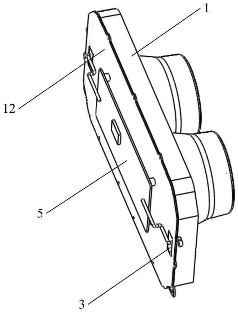
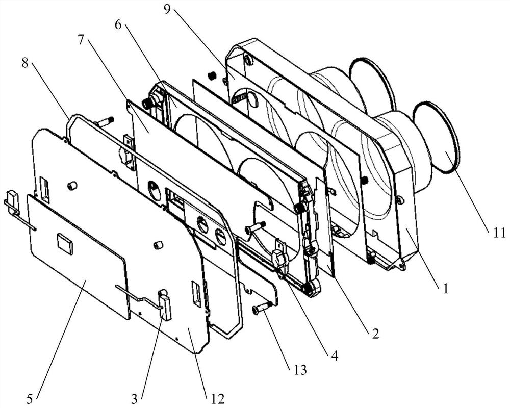
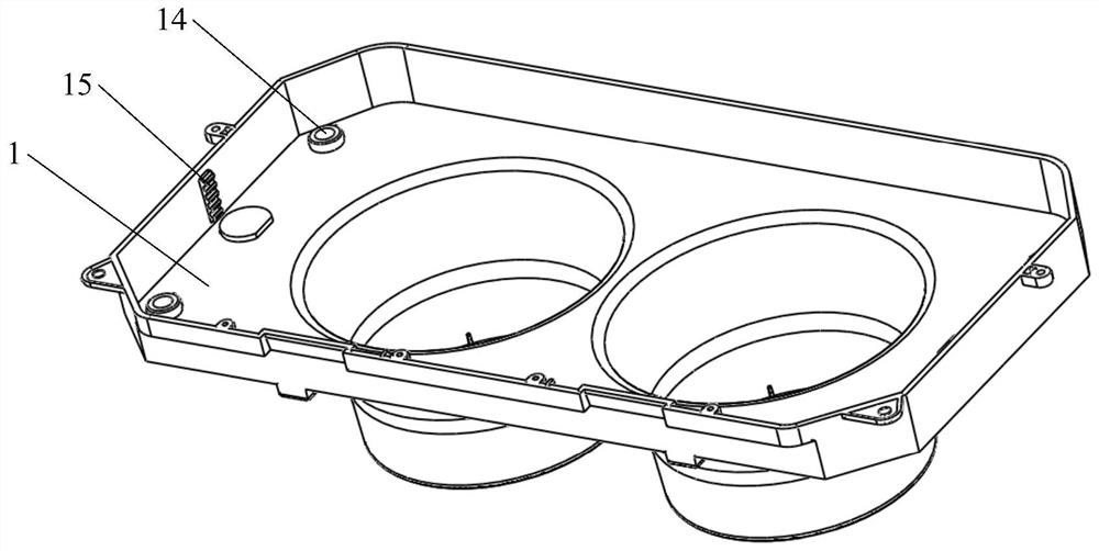
[0038] Please refer to Figure 1-Figure 7 , figure 1 A schematic structural diagram of a head-mounted display device provided for a specific embodiment of the present invention; figure 2 for figure 1 explosion map; image 3 for figure...


PUM


Abstract

The invention discloses a head-mounted display device, which comprises: a lens barrel, a lens is arranged at the front end of the lens barrel; a movable display screen is arranged in the lens barrel; a first magnet fixedly connected with the lens barrel and The connected second magnet, at least one of the first magnet and the second magnet is an electromagnet; the control chip connected with the electromagnet and used to control the on and off of the electromagnet and the direction of the current flow, to use the first magnet and the second magnet The same pole repels and the opposite pole attracts each other of the second magnet to drive the display screen close to or away from the lens. The head-mounted display device adjusts the focal length through the magnetic force between the first magnet and the second magnet, so as to meet the wearing requirements of people with different eyesight and improve the comfort of user experience.

Description

technical field [0001] The present invention relates to the technical field of wearable devices, and more specifically, to a head-mounted display device. Background technique [0002] For head-mounted display devices, such as AR / VR glasses or AR / VR head-mounted displays, due to the different visual conditions of users, these devices need to adjust the focal length when using them. The focal length is a measure of the concentration or divergence of light in the optical system. The measurement method refers to the distance from the optical center of the lens to the focal point where the light gathers when parallel light is incident. In head-mounted display devices, the focal length can be thought of as the distance from the lens to the screen. [0003] Considering the simplicity of the structure, the focal length of most head-mounted display devices is fixed and cannot be adjusted. In the existing technology, different face-fitting foam components are usually replaced to meet...

Claims


Application Information

Patent Timeline
Patent Type & Authority Patents(China)
IPC IPC(8): G02B27/01
CPCG02B27/0172G02B27/0176G02B2027/0178
Inventor 刘威郑元景姜滨迟小羽
Owner GEER TECH CO LTD
Why Eureka
Try Eureka