burner

A combustion device and burner technology, applied in the direction of burners, combustion types, combustion methods, etc., can solve problems such as limited infrared intensity and imperfect design of infrared heat source devices

Active Publication Date: 2021-07-06
GRAND MATE
View PDF8 Cites 0 Cited by
  • Summary
  • Abstract
  • Description
  • Claims
  • Application Information

AI Technical Summary

Problems solved by technology

However, the cover plate will cause the infrared rays emitted by the infrared ray generating net to be blocked by the cover plate 84, so that when the infrared rays scattered by the infrared heat source device act on the object, the intensity of infrared rays received by the object per unit area is relatively limited.
[0004] Therefore, its design of the existing infrared heat source device is still imperfect, and there is room for improvement.

Method used


Image

  • burner
  • burner
  • burner

Examples


Embodiment Construction

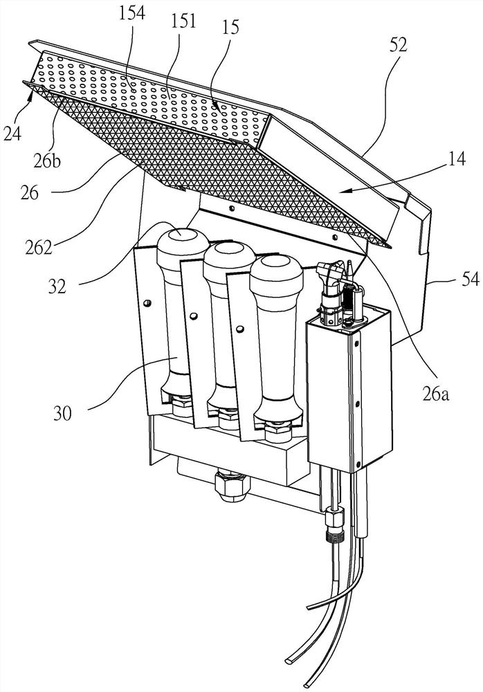
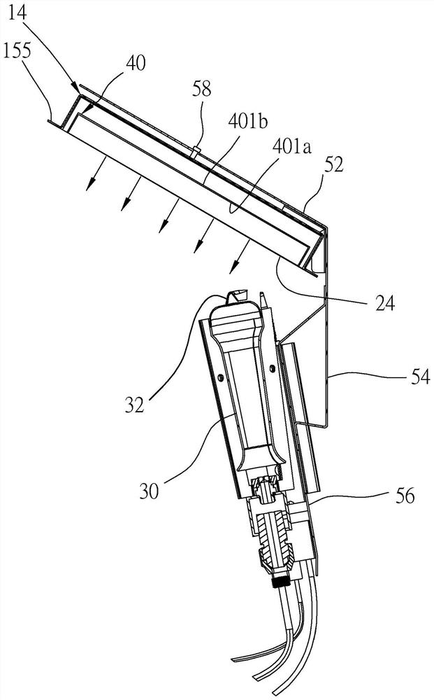
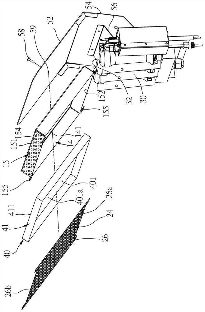
[0028] In order to illustrate the present invention more clearly, preferred embodiments are given and detailed descriptions are given below in conjunction with drawings. Please refer to Figure 1 to Figure 3 Shown is the combustion device 100 of the first preferred embodiment of the present invention, the combustion device 100 includes a support assembly 10, an infrared ray generating net 24, an infrared reflection plate 40 and at least one burner 30, wherein:

[0029] Such as image 3 As shown, the support assembly 10 includes a rear shield 14, the rear shield 14 is inclined and is made of metal material, and the rear shield 14 has a flat and rectangular rear plate 141, and the rear shield 14 includes a ring wall 15 is connected to the periphery of the rear plate 14, the ring wall 15 has an upper side wall 151 and a lower side wall 152, the upper side wall 151 is connected to the top edge of the rear plate 141, and the upper side wall 151 has a plurality of holes 154 commun...


PUM


Abstract

A combustion device comprising at least one burner, a supporting component, and an infrared ray generating net; wherein, the burner has a fire outlet; the infrared ray generating net is arranged on the rear shield of the supporting component and corresponds to the fire outlet, and the infrared ray The production net is heated by the flame produced by the fire outlet. In this way, a heat source that generates open flame and infrared rays is formed to effectively increase the heating intensity and achieve the purpose of uniform heating.

Description

【Technical field】 [0001] The present invention relates to heating devices; in particular, it refers to a combustion device that uses infrared rays to heat objects. 【Background technique】 [0002] Generally speaking, a gas burning device burns gas to generate a flame, and uses the flame to heat objects. When using a gas combustion device to heat an object, since the heat conduction path is from the surface of the object to the interior of the object, the surface of the object is often heated more while the interior of the object is less heated, resulting in uneven heating of the object as a whole. [0003] In order to solve the above problems, an infrared heat source device is currently known, such as the combustion device in Chinese Patent No. M563762, which uses the property that infrared rays can penetrate objects, so that the surface of the object and the inside of the object can be heated simultaneously. In this patent, the burner 42 outputs a flame, so that the infrare...

Claims


Application Information

Patent Timeline
Patent Type & Authority Patents(China)
IPC IPC(8): F23D14/14F23D14/46
CPCF23D14/14F23D14/46
Inventor 黃重景黃锦颖黄信铭黃信雄叶严仁林冠州
Owner GRAND MATE
Why Eureka
Try Eureka