
Ball forming device and preparation method of spherical carrier

A spherical carrier and ball-forming technology, which is applied in the direction of liquid separation into bead droplets and granulation, can solve the problems of reducing sphericity, tailing, ball wear, etc., to improve sphericity and wear resistance, and eliminate tailing phenomenon. Effect

Active Publication Date: 2022-05-03
CHINA PETROLEUM & CHEM CORP +1
View PDF10 Cites 0 Cited by
  • Summary
  • Abstract
  • Description
  • Claims
  • Application Information

AI Technical Summary

Problems solved by technology

[0004] In the process of using the existing ball drop method to drop the ball, the tailing phenomenon will occur during the vertical drop of the ball into the ball column, so the sphericity is reduced, which eventually leads to excessive wear of the ball during use

Method used


Image

  • Ball forming device and preparation method of spherical carrier
  • Ball forming device and preparation method of spherical carrier
  • Ball forming device and preparation method of spherical carrier

Examples


Embodiment approach

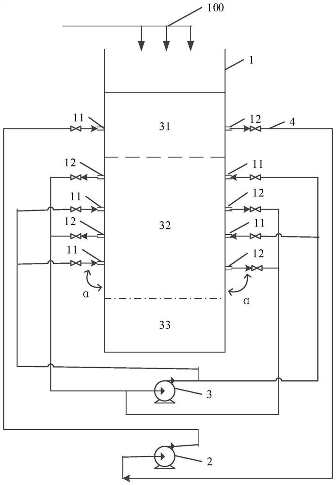
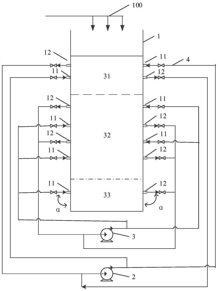
[0023] An embodiment, preferably, as figure 2 As shown, a row of liquid inlets 11 is arranged on the side wall of the collection area 33 of the container body 1 , and a row of liquid outlets 12 is oppositely arranged on the side wall of the other side. Two rows of liquid inlets 11 and liquid outlets 12 are arranged alternately on one side of the ball forming area, and two rows of liquid outlets 12 and liquid inlets 11 are alternately arranged on the other side of the sidewall. see specific Figure 4 , Figure 5 . The liquids in the solidification zone and the collection zone can be the same or two with similar properties.

[0024] In the present invention, the ball forming liquid circulation mechanism is used to circulate the ball forming liquid in the container body through the liquid inlet and the liquid outlet. Such as Figure 1-2 As shown, the first ball forming liquid circulation mechanism 2 may include a pipeline and a first circulation pump, the liquid inlet 11 of...

example 1

[0044] Cuboid-shaped oily ammonia column (container body) is used to form balls. The oily ammonia column is 2m long, 55cm wide, and 2m high. In addition to the oily ammonia column structure, the oil phase and ammonia water phase are used to form balls, solidification areas and collection areas. The heights are the same as in Comparative Example 1. Schematic diagram of the ball forming device figure 1 shown.

[0045] Set a row of liquid outlets at heights of 20cm, 90cm, and 190cm from the bottom of the oil ammonia column on the side wall of the oil ammonia column length direction, and set a row of liquid inlets at 55cm and 125cm heights; in the length direction of the oil ammonia column The side wall on the other side is respectively provided with a row of liquid inlets at heights of 20cm, 90cm, and 190cm from the bottom of the oil and ammonia column, and a row of liquid outlets is respectively arranged at heights of 55cm and 125cm. Each row of liquid inlets includes 10 liqui...

example 2

[0047] The method of example 1 adopts the container body of cuboid shape to carry out balling, and the structural representation of balling device is as follows figure 1 shown. Differently, the sphere-forming liquid was replaced with liquid paraffin in Comparative Example 2, the thickness of the oil phase was 195 cm, and the heights of the sphere-forming zone, solidification zone, and collection zone were all the same as the oil ammonia column. The sphericity of the pellets obtained after drop ball forming, water washing, drying and roasting is 0.970.


PUM

PropertyMeasurementUnit
angleaaaaaaaaaa
lengthaaaaaaaaaa
widthaaaaaaaaaa

Abstract

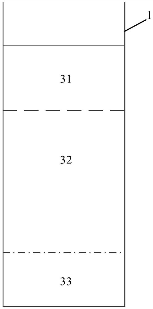
The invention relates to a spherical carrier ball forming device and preparation method, comprising a container body for containing a ball forming liquid and a ball forming liquid circulation mechanism located outside the container body, the container body is divided into components from top to bottom The ball area, the solidification area and the collection area, the top is provided with the top opening for dripping the slurry droplets; at least one row of liquid inlets are arranged alternately along the vertical direction on the side walls on the opposite sides of the ball forming area and the curing area of ​​the container body And a row of liquid outlets, the ball forming liquid enters the container body from the liquid inlet through the pipeline, and is discharged from the container body from the liquid outlet, and then returns to the liquid inlet. The ball forming liquid in the ball forming area is circulated through the first ball forming liquid circulation mechanism, and the curing area and the ball forming liquid in the collection area are circulated through the second ball forming liquid circulation mechanism. The device and method of the invention can eliminate the trailing phenomenon of the slurry drop, and improve the sphericity and wear resistance of the spherical carrier.

Description

technical field [0001] The invention relates to the field of spherical carrier preparation, in particular to a spherical carrier forming device and a preparation method. Background technique [0002] Dropping spheres is an important method for preparing spherical particles, which is widely used in the preparation of catalyst spherical particles, such as alumina column dropping spheres. [0003] CN 205095741 U and CN 205095740 U introduce the technological process of the current advanced spherical oxide forming device in detail. The ball-forming columns in the two patents are all simple vertical containers, the upper layer of the ball-forming column is an oil phase, and the lower layer is a solidified liquid. [0004] In the process of using the existing ball dropping method to drop the ball, the tailing phenomenon will occur during the vertical drop of the ball into the ball column, so the sphericity is reduced, which eventually leads to excessive wear of the ball during us...

Claims


Application Information

Patent Timeline
Patent Type & Authority Patents(China)
IPC IPC(8): B01J2/06
CPCB01J2/06
Inventor 于宁臧高山王嘉欣张玉红王涛丁璟
Owner CHINA PETROLEUM & CHEM CORP
Learn More