
Apparatus achieving dynamic vacuum degassing and use method of same

A vacuum degassing and dynamic technology, applied in measurement devices, liquid degassing, separation methods, etc., can solve the problems of high overall complexity and strict environmental temperature requirements, achieve high degassing efficiency and improve the effect of escape rate

Inactive Publication Date: 2020-03-10
福建和盛高科技产业有限公司
View PDF4 Cites 1 Cited by
  • Summary
  • Abstract
  • Description
  • Claims
  • Application Information

AI Technical Summary

Problems solved by technology

[0003] The present invention improves the above-mentioned problems, that is, the technical problem to be solved by the present invention is that the oil-gas separation device in the existing gas chromatograph has strict requirements on the ambient temperature, and the overall complexity is high

Method used

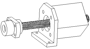

Image

  • Apparatus achieving dynamic vacuum degassing and use method of same
  • Apparatus achieving dynamic vacuum degassing and use method of same
  • Apparatus achieving dynamic vacuum degassing and use method of same

Examples


Embodiment Construction

[0033] The present invention will be described in further detail below in conjunction with the accompanying drawings and specific embodiments.

[0034] Such as Figure 1-7 As shown, the device provided by the present invention to realize dynamic vacuum degassing, such as figure 1 shown, including:

[0035] Four two-way solenoid valves, the two-way solenoid valve is a two-position two-way structure; the four two-way solenoid valves include solenoid valve V01, solenoid valve V02, solenoid valve V03, solenoid valve V04,

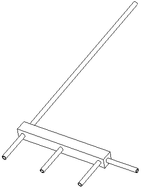
[0036] A five-way connection pipeline T001, on which there are four oil inlet and outlet pipes connected to the four solenoid valve inlet and outlet ports, and one oil inlet and outlet pipe connected to the degassing cylinder;

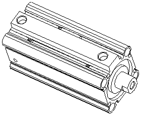
[0037] A degassing cylinder CQ01, which is equipped with: an oil inlet and outlet connected to an inlet and outlet oil pipe of the five-way connection pipeline T001, a sample gas outlet, a breathing port, and a telescopic rod connected...


PUM


Abstract

The invention provides an apparatus achieving dynamic vacuum degassing and a use method of same. The apparatus includes a five-way connection pipe, four two-way electromagnetic valves, a degassing cylinder and a passive cylinder, wherein the two-way electromagnetic valves have a two-position connection structure; four ways of the five-way connection pipe are connected respectively to four oil inlet / outlet pipes of the four two-way electromagnetic valves, the rest one way of the five-way connection pipe is connected to the oil inlet / outlet of the degassing cylinder through a connection pipe; the degassing cylinder also has a sample gas outlet; a telescopic rod of the degassing cylinder is telescoped under driving by a driving device; a limit switch for controlling the movement of the telescopic rod is arranged on the degassing cylinder; the oil inlet / outlet of the passive cylinder is connected to one of the two-way electromagnetic valves through an oil path connection pipe. By means ofthe precise cooperation of the driving device and the degassing cylinder, precise metering of detection oil is achieved. The detection oil flows forth and back between the degassing cylinder and the passive cylinder, so that escape rate and separation efficiency of gas are improved, and extremely high degassing efficiency is achieved.

Description

technical field [0001] The invention relates to a device for realizing dynamic vacuum degassing and a use method thereof, in particular to a device for separating characteristic gases dissolved in transformer oil applied to gas phase oil chromatographic on-line monitoring equipment in substations. Background technique [0002] The oil and gas separation device is the leading core component in the gas chromatograph, and the dissolved gas in the oil can be separated from the oil through the oil separation operation. The degassing rate and consistency of oil and gas separation are of great significance for improving the accuracy and stability of food analysis, and it is widely used in online monitoring equipment for oil chromatography in substations. At present, there are two main ways for online monitoring devices to realize oil-gas separation: vacuum degassing method realized by vacuum pump and headspace degassed method realized by circulating oil pump or gear piston pump. T...

Claims


Application Information

Patent Timeline
Patent Type & Authority Applications(China)
IPC IPC(8): B01D19/00G01N30/14
CPCB01D19/0031G01N30/14
Inventor 林尚丰陈珂林立锋
Owner 福建和盛高科技产业有限公司
Learn More