
Image tagging method, device, computer system and readable storage medium

An image labeling and image technology, applied in the field of communication, can solve the problems of reducing the labeling accuracy of the lesion area, improving the fatigue intensity of doctors, and uneven boundaries, etc., achieving the effect of convenient labeling work, improved recognition, and reduced fatigue intensity

Active Publication Date: 2022-03-29
PING AN TECH (SHENZHEN) CO LTD
View PDF0 Cites 0 Cited by
  • Summary
  • Abstract
  • Description
  • Claims
  • Application Information

AI Technical Summary

Problems solved by technology

[0003] However, the current brush function only supports drawing lines on the image, but the labeling of the lesion area usually requires the end point of the brush to coincide with the starting point, so that the doctor can only complete it by zooming in on the image and slowly moving the brush to its starting point; Not only is the efficiency low, but it also brings great inconvenience to the doctor and increases the fatigue strength of the doctor; at the same time, because once the line is drawn, only a single boundary point can be moved, resulting in uneven boundaries, thus reducing the need for Labeling accuracy of lesion area

Method used


Image

  • Image tagging method, device, computer system and readable storage medium
  • Image tagging method, device, computer system and readable storage medium
  • Image tagging method, device, computer system and readable storage medium

Examples


Embodiment 1

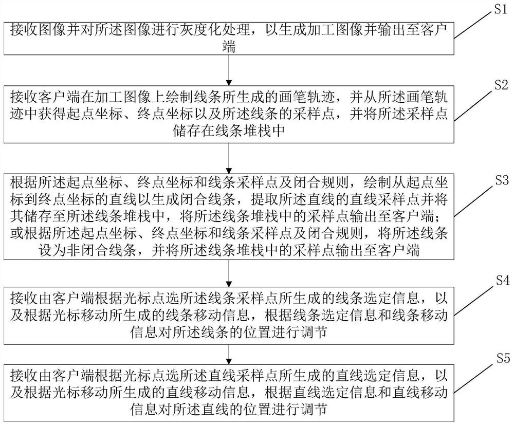
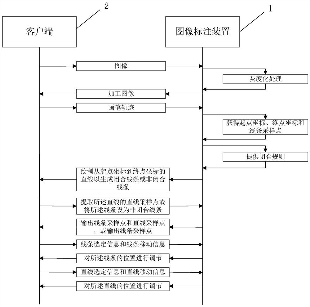
[0062] see figure 1 with figure 2 , an image tagging method of the present embodiment, using the image tagging device 1, includes the following steps:

[0063] S1: Receive an image and perform grayscale processing on the image to generate a processed image and output it to the client 2;

[0064] S2: Receive the brush trajectory generated by the client 2 drawing lines on the processed image, and obtain the starting point coordinates, end point coordinates and sampling points of the line from the brush trajectory, and store the sampling points in the line stack ; Wherein, the brush trajectory is a coordinate set used to describe the trajectory coordinates of the line;

[0065] S3: According to the start point coordinates, end point coordinates, line sampling points and closing rules, draw a straight line from the start point coordinates to the end point coordinates to generate a closed line, extract the straight line sampling points of the straight line and store them in the ...

Embodiment 2

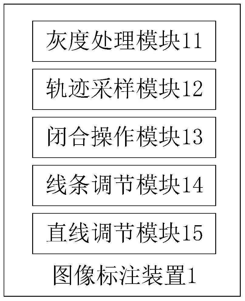
[0134] see image 3 , an image tagging device 1 of this embodiment, comprising:

[0135] A grayscale processing module 11, configured to receive an image and perform grayscale processing on the image to generate a processed image and output it to the client 2;

[0136] The trajectory sampling module 12 is used to receive the brush trajectory generated by the client 2 drawing lines on the processed image, and obtain the starting point coordinates, the end point coordinates and the sampling points of the lines from the brush trajectory, and transfer the sampling points to Stored in the line stack; wherein, the brush trajectory is a coordinate set used to describe the trajectory coordinates of the line;

[0137] The closing operation module 13 is used to draw a straight line from the starting point coordinates to the end point coordinates to generate a closed line according to the starting point coordinates, the ending point coordinates, the line sampling points and the closing ru...

Embodiment 3

[0143] In order to achieve the above object, the present invention also provides a computer system, the computer system includes a plurality of computer equipment 3, the components of the image labeling device 1 of the second embodiment can be dispersed in different computer equipment, and the computer equipment can be the execution program Smartphones, tablet computers, laptops, desktop computers, rack servers, blade servers, tower servers or rack servers (including independent servers, or server clusters composed of multiple servers), etc. The computer equipment in this embodiment at least includes but is not limited to: a memory 31 and a processor 32 that can communicate with each other through a system bus, such as Figure 4 shown. It should be pointed out that, Figure 4 Only a computer device is shown with the components - but it should be understood that implementing all of the illustrated components is not a requirement and that more or fewer components may instead be...


PUM


Abstract

The invention discloses an image labeling method, device, computer system and readable storage medium, comprising the following steps: receiving an image and performing grayscale processing on the image to generate a processed image; receiving a brush trajectory, and obtaining starting point coordinates from the brush trajectory , end point coordinates, and sampling points of the line, and store the sampling points in the line stack; draw a straight line from the starting point coordinates to the end point coordinates to generate a closed line according to the starting point coordinates, end point coordinates, line sampling points and closing rules, and extract the line's Line sampling points are stored in the line stack, and the sampling points in the line stack are output to the client; or according to the starting point coordinates, end point coordinates, line sampling points and closure rules, the line is set as an unclosed line, and the line The sampling points in the stack are output to the client; receive line selection information and line movement information, and adjust the position of the line. The invention improves the labeling efficiency and the accuracy of labeling the lesion area.

Description

technical field [0001] The invention relates to the field of communication technology, in particular to an image labeling method, device, computer system and readable storage medium. Background technique [0002] At present, when doctors mark the lesion area of ​​the image, they usually use the brush function of the common drawing tool to draw lines on the outer contour of the lesion area, so as to achieve the purpose of marking the lesion area; [0003] However, the current brush function only supports drawing lines on the image, but the labeling of the lesion area usually requires the end point of the brush to coincide with the starting point, so that the doctor can only complete it by zooming in on the image and slowly moving the brush to its starting point; Not only is the efficiency low, but it also brings great inconvenience to the doctor and increases the fatigue strength of the doctor; at the same time, because once the line is drawn, only a single boundary point can...

Claims


Application Information

Patent Timeline
Patent Type & Authority Patents(China)
IPC IPC(8): G16H30/40G16H30/20G06T11/20
CPCG16H30/40G16H30/20G06T11/203
Inventor 陈超王瑞豪李明杰黄凌云刘玉宇
Owner PING AN TECH (SHENZHEN) CO LTD
Learn More