
A data fusion method and device

A data fusion and target data technology, applied in the field of data processing, can solve the problems of inaccurate detection results, adverse effects of millimeter wave radar detection, and reduce object detection accuracy, so as to overcome the low detection accuracy.

Active Publication Date: 2022-04-15
NEUSOFT REACH AUTOMOBILE TECH (SHENYANG) CO LTD
View PDF6 Cites 0 Cited by
  • Summary
  • Abstract
  • Description
  • Claims
  • Application Information

AI Technical Summary

Problems solved by technology

[0003] However, the inventor found through research that, no matter whether the millimeter-wave radar or the laser radar is used to detect the relative position of other vehicles around and the own vehicle, the detection is inaccurate.
Specifically, since the millimeter-wave radar uses the reflection of the target object on the electromagnetic wave to find and measure the position of the surrounding objects, while the vehicle is driving, the external environment full of clutter will have a negative impact on the detection of the millimeter-wave radar, reducing the detection of objects. Detection accuracy
At the same time, it takes a certain amount of computing time to obtain data through point cloud recognition through lidar, and during the calculation process of the point cloud recognition algorithm, the own vehicle and other surrounding vehicles still continue to move, so the other vehicles obtained by the point cloud recognition algorithm and There is a certain delay difference between the relative displacement of the self-vehicle and the actual relative displacement, that is, the relative displacement of other vehicles and the self-vehicle obtained by the point cloud recognition algorithm has a lag and inaccurate problem, which will also lead to inaccurate detection results

Method used


Image

  • A data fusion method and device
  • A data fusion method and device
  • A data fusion method and device

Examples


no. 1 example

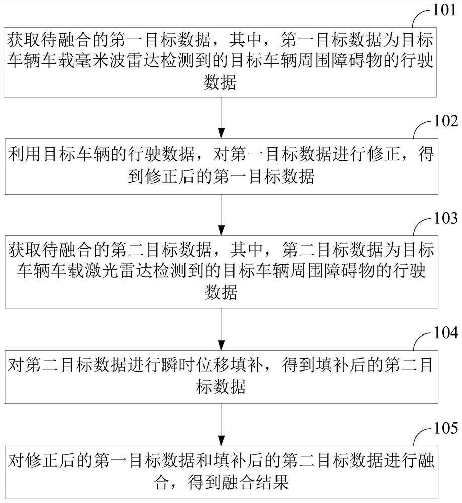
[0075] see figure 1 , which is a schematic flowchart of a data fusion method provided in this embodiment, the method includes the following steps:

[0076] S101: Acquire first target data to be fused, wherein the first target data is driving data of obstacles around the target vehicle detected by the vehicle-mounted millimeter-wave radar of the target vehicle.

[0077] In this embodiment, any vehicle that uses this embodiment to achieve data fusion is defined as the target vehicle. In order to realize the fusion of driving data that detects obstacles around the target vehicle, it is first necessary to obtain the first target data to be fused .

[0078] Wherein, the first target data refers to the driving data of obstacles around the target vehicle detected by the vehicle-mounted millimeter-wave radar of the target vehicle. An optional implementation is that the driving data of obstacles around the target vehicle may include Obstacle position information and speed information...

no. 2 example

[0122] This embodiment will introduce a data fusion device, and for relevant content, please refer to the foregoing method embodiments.

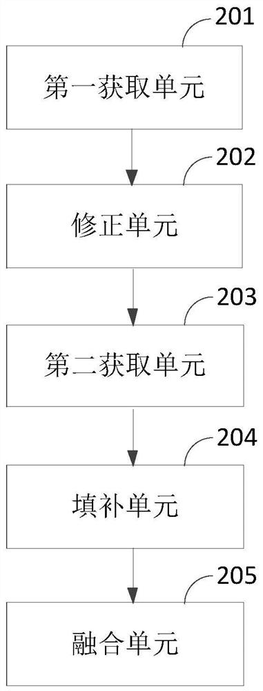
[0123] see figure 2 , which is a schematic diagram of the composition of a data fusion device provided in this embodiment, the device includes:

[0124] The first acquisition unit 201 is configured to acquire the first target data to be fused, the first target data being the driving data of obstacles around the target vehicle detected by the vehicle-mounted millimeter-wave radar of the target vehicle;

[0125] A correction unit 202, configured to use the driving speed of the target vehicle to correct the first target data to obtain corrected first target data;

[0126] The second acquisition unit 203 is configured to acquire the second target data to be fused, the second target data being the driving data of obstacles around the target vehicle detected by the vehicle-mounted lidar of the target vehicle;

[0127] A padding unit 204, config...


PUM


Abstract

This application discloses a data fusion method and device, by correcting the driving data of the obstacles around the target vehicle detected by the millimeter-wave radar and the driving data of the obstacles around the target vehicle detected by the laser radar, and then performing the correction result Fusion processing, so that more accurate obstacle detection results can be matched. The method includes: firstly, correcting the driving data of the obstacles around the target vehicle detected by the millimeter-wave radar to obtain the corrected first target data, and performing a correction on the driving data of the obstacles around the target vehicle detected by the laser radar. Instantaneous displacement filling to obtain the filled second target data, and then facilitate EKF to perform fusion processing on the obtained corrected first target data and filled second target data, so as to determine the surrounding area of ​​the target vehicle according to the fusion result Obstacle detection results.

Description

technical field [0001] The present application relates to the technical field of data processing, in particular to a data fusion method and device. Background technique [0002] In the field of autonomous driving, especially unmanned driving, it is necessary to clarify the relative displacement of other vehicles and the own vehicle. At present, the self-vehicle generally detects the relative positions of other surrounding vehicles and the self-vehicle through millimeter-wave radar and lidar. [0003] However, the inventor found through research that, no matter whether the millimeter-wave radar or the laser radar is used to detect the relative positions of other surrounding vehicles and the self-vehicle, the detection is inaccurate. Specifically, since the millimeter-wave radar uses the reflection of the target object on the electromagnetic wave to find and measure the position of the surrounding objects, while the vehicle is driving, the external environment full of clutter...

Claims


Application Information

Patent Timeline
Patent Type & Authority Patents(China)
IPC IPC(8): G01S13/06G01S13/58G01S17/06G01S17/58G06F17/10
CPCG01S13/06G01S13/58G01S17/06G01S17/58G06F17/10
Inventor 栾欣泽
Owner NEUSOFT REACH AUTOMOBILE TECH (SHENYANG) CO LTD
Learn More