Vertical shaft construction stepping-type template based on hydraulic drive and working method thereof

A stepping and formwork technology, which is applied in shaft equipment, earthwork drilling, shaft lining, etc., can solve the problems of high labor intensity, restriction of shaft excavation speed, and low integration, so as to improve shaft excavation efficiency and enhance work safety reliability effect

Pending Publication Date: 2020-03-06
CHINA COAL NO 5 CONSTR +1
View PDF3 Cites 3 Cited by
  • Summary
  • Abstract
  • Description
  • Claims
  • Application Information

AI Technical Summary

Problems solved by technology

[0002] At present, during the mine shaft excavation process, the formwork supporting the reinforced concrete is mostly moved manually, and the frame is manually moved every time a certain distance of concrete pouring is completed. This operation method takes a long time and greatly restricts the speed of shaft excavation.
At the same time, the labor intensity of the workers is high, and because the working environment in the deep well is very bad, the life safety of the staff is threatened
There are still some deficiencies in the current related schemes: the hydraulic stepping shaft formwork support device (CN102305076A) has low system integration, inconvenient installation and debugging, the overall efficiency is not high, and the work cycle cannot be formed; the stepping hydraulically operated integral metal formwork (CN101660421A ) adopts the stepping ring structure to make the operation complicated and low in efficiency; the shaft has no suspension and the step-down integral metal formwork (CN107083976A) can only realize the movement through the longitudinal support and guidance, and cannot avoid the circumferential movement of the upper and lower formwork during the movement

Method used


Image

  • Vertical shaft construction stepping-type template based on hydraulic drive and working method thereof
  • Vertical shaft construction stepping-type template based on hydraulic drive and working method thereof
  • Vertical shaft construction stepping-type template based on hydraulic drive and working method thereof

Examples


Embodiment Construction

[0033] The invention will be further described below in conjunction with the embodiments in the drawings.

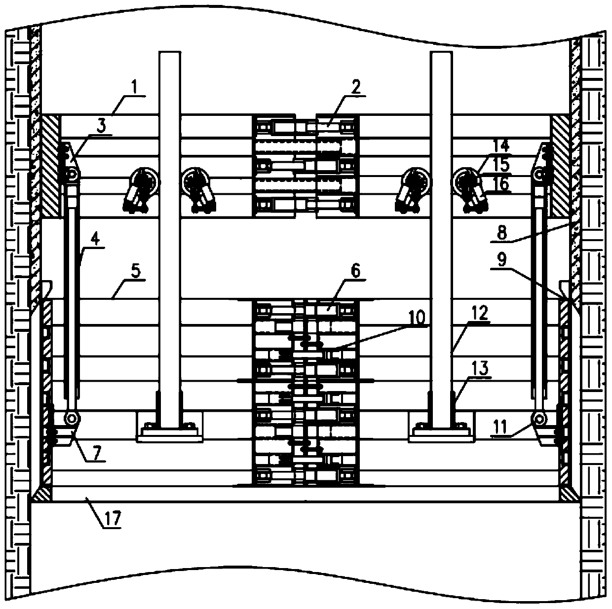
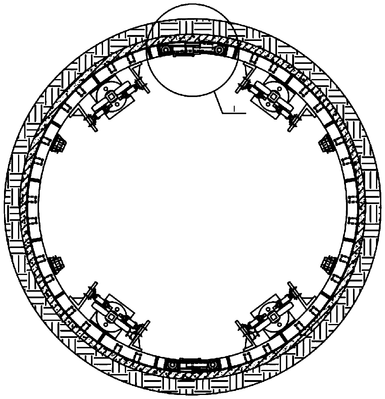
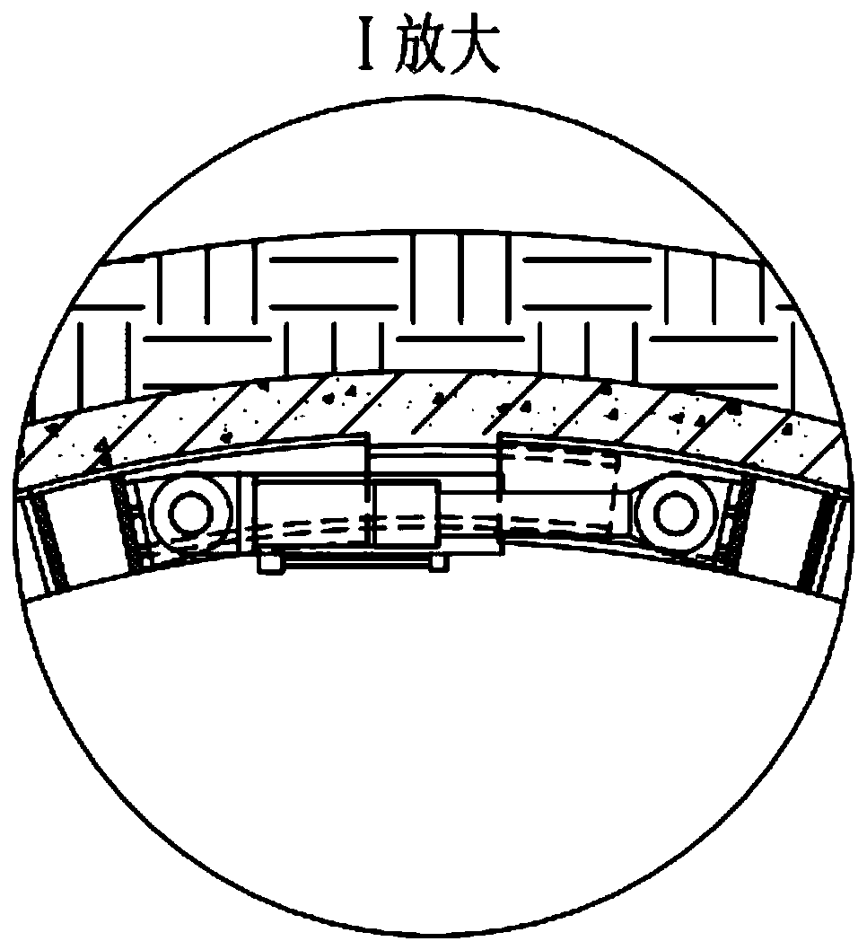
[0034] Such as figure 1 As shown, a stepping template for vertical shaft construction based on hydraulic drive of the present invention includes two parts in structure: one is the upper support shoe part, which is realized by extending or retracting the piston rod of the support shoe cylinder 2 1. Move away or move towards each other to realize the tightening of the concrete shaft wall 8 or the separation of the concrete shaft wall 8; the second is the stepping template part, the stepping cylinder 4 piston rod is extended or retracted to drive the template 5 to move downward; at the same time the template 5 is inside The expansion and contraction of the template support cylinder 2 can be used for compression and demoulding during the concrete pouring of the well wall; the alternate action combination of the support shoe cylinder, the stepping cylinder and the support cylinde...


PUM


Abstract

The invention relates to a vertical shaft construction stepping-type template based on hydraulic drive and a working method thereof. The vertical shaft construction stepping-type template comprises two parts, one is an upper expandable shoe part, expanding a concrete well wall or separating from the concrete well wall of upper expandable shoes is realized through extending or retracting a piston rod of a expandable shoe oil cylinder; and the other is a template body part, template bodies can move downward or upward through extending or retracting the piston rod of a step oil cylinder, at the same time, the expansion of a template body expanding oil cylinder can press the template bodies and release the template bodies when well wall concrete is poured, and the combination of alternate actions of the expandable shoe oil cylinder, the step oil cylinder and the expanding oil cylinder can realize the automatic circulation of the vertical shaft construction process. According to the vertical shaft construction stepping-type template based on hydraulic drive and the working method thereof, the harsh operation environment of a deep well can be well adapted, and the vertical shaft construction efficiency and safety reliability are improved.

Description

Technical field [0001] The invention relates to the technical field of mine construction, in particular to a stepping template for vertical shaft construction based on hydraulic drive and a working method thereof. Background technique [0002] At present, in the process of mine shaft excavation, most of the formwork supporting reinforced concrete is moved manually, and the frame is moved manually every time the concrete is poured for a certain distance. This operation method takes a long time and greatly restricts the speed of shaft excavation. At the same time, the labor intensity of workers is high, and because the working environment in deep wells is very bad, the lives of the workers are threatened. There are still some shortcomings in the current related solutions: the hydraulic stepping shaft formwork support device (CN102305076A) has low system integration, inconvenient installation and debugging, and the overall efficiency is not high, and it cannot form a working cycle; ...

Claims


Application Information

Patent Timeline
IPC IPC(8): E21D5/12E21D5/04
CPCE21D5/12E21D5/04
Inventor 王继全张彦江军马传银赵继云曹超黄笛宋培洲庄小青杨晓信邓维标王云飞张鹤
Owner CHINA COAL NO 5 CONSTR
Why Eureka
Try Eureka