
Vacuum strobe frequency observation window

A technology of observation window and glass observation window, which is applied in the field of vacuum strobe observation window, can solve the problems that the operator cannot see clearly and blocks the viewer's sight, and achieves the effect of convenient observation

Pending Publication Date: 2020-03-06
宝鸡亚光机械有限公司
View PDF0 Cites 1 Cited by
  • Summary
  • Abstract
  • Description
  • Claims
  • Application Information

AI Technical Summary

Problems solved by technology

[0002] In the fields of vacuum smelting, vacuum heat treatment, and ion sputtering, the conditions in the vacuum chamber are observed through the strobe observation window. When the metal is melted, metal particles will be ejected from the surface, and the gas or low-melting point metal originally dissolved in the metal will also be released. It can be ejected, and these ejected objects can fly a long distance in a vacuum state. When they are sputtered on the vacuum observation window glass, they will form a film, which will block the observer's sight and make the operator unable to see the vacuum clearly. indoor situation

Method used


Image

  • Vacuum strobe frequency observation window
  • Vacuum strobe frequency observation window
  • Vacuum strobe frequency observation window

Examples


Embodiment Construction

[0020] The present invention will be described in further detail below in conjunction with specific examples, but the embodiments of the present invention are not limited thereto.

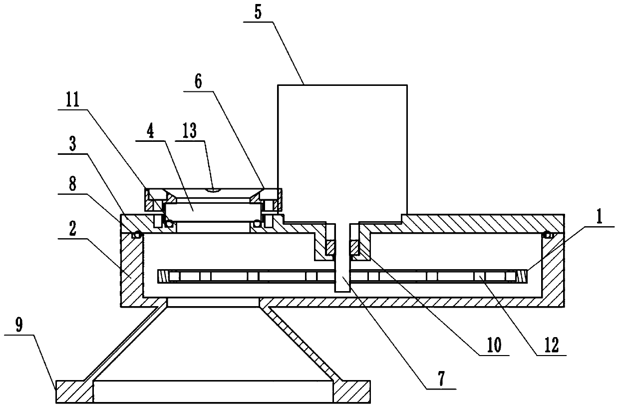
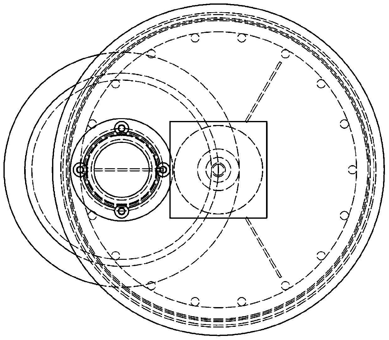
[0021] See also figure 1 , figure 2 and image 3 , the embodiment of the present invention provides a vacuum strobe observation window, including: a rotating disc 1, a housing 2, an upper cover 3, a glass observation window 4, and a motor 5; wherein,

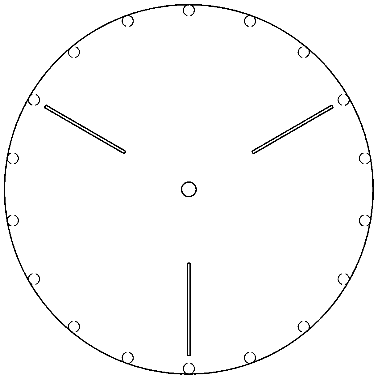
[0022] The rotating disk 1 is located in the housing 2 and is surrounded by two layers of disks, so that a cavity is formed between the upper and lower layers of disks, and the upper and lower layers of disks are centered on the center of the circle, and the center is symmetrically arranged with two The straight seam above the strip, and make the straight seams set on the upper and lower discs one-to-one.

[0023] Preferably, three straight slits are provided; the length of the straight slits is less than the radius of the rotating disc 1 , and t...


PUM

PropertyMeasurementUnit
widthaaaaaaaaaa
diameteraaaaaaaaaa
thicknessaaaaaaaaaa

Abstract

The invention discloses a vacuum strobe frequency observation window comprising a rotating disc, a shell, an upper cover, a glass observation window and a motor. The rotating disc is located in the shell and is defined by two discs on the two layers of discs up and down, a cavity is formed between the two layers of discs up and down, the two layers of discs up and down use the circle centers as centers, each center is symmetrically provided with two or more straight seams, and the straight seams arranged on the two layers of discs up and down are in one-to-one correspondence; the glass observation window is fixed on the outer side of the upper cover, the motor is fixed on the outer side of the upper cover, a main shaft of the motor passes through the upper cover and extends into the shell,the main shaft passes through the rotating disc and is fixedly connected to the rotating disc, the upper cover and one side of the shell are fixedly connected, and the other side of the shell is fixedly connected to a vacuum chamber. By means of the vacuum strobe frequency observation window, splashing can stopped, an operator can conveniently observe the condition inside the vacuum chamber, thearea of the seams of the rotating discs is smaller than the area of the rotating discs, light capable of passing through the seams is greatly reduced, the light shielding effect is achieved, and observation is facilitated.

Description

technical field [0001] The invention belongs to the technical field of vacuum smelting, and in particular relates to a vacuum strobe observation window. Background technique [0002] In the fields of vacuum smelting, vacuum heat treatment, and ion sputtering, the conditions in the vacuum chamber are observed through the strobe observation window. When the metal is melted, metal particles will be ejected from the surface, and the gas or low-melting point metal originally dissolved in the metal will also be released. It will eject, and these ejections can fly a long distance in a vacuum state. When they are sputtered on the vacuum observation window glass, they will form a film, which will block the observer's line of sight and make the operator unable to see the vacuum clearly. indoor situation. Contents of the invention [0003] In order to solve the above-mentioned problems in the prior art, the present invention provides a vacuum stroboscopic observation window. The te...

Claims


Application Information

Patent Timeline
Patent Type & Authority Applications(China)
IPC IPC(8): C23C14/52C23C14/34C21D9/00C21D1/773F27D21/02
CPCC23C14/52C23C14/3442C21D1/773C21D9/0006F27D21/02
Inventor 王绪生胡宗式
Owner 宝鸡亚光机械有限公司
Learn More