
Electromagnetic wave shield box

A shielding box and electromagnetic wave technology, which is applied in the fields of magnetic/electric field shielding, shielding efficiency measurement, circuits, etc., can solve the problems of reduced accuracy, unavoidable, and reduced performance test accuracy, and achieve the effect of achieving accuracy and suppressing the generation of standing waves

Active Publication Date: 2020-03-03
ANRITSU CORP
View PDF4 Cites 2 Cited by
  • Summary
  • Abstract
  • Description
  • Claims
  • Application Information

AI Technical Summary

Problems solved by technology

However, in the OTA test of such a DUT, the radio waves radiated from each coupling antenna, especially from the coupling antenna facing each other, or the reflected waves of the radio waves by the DUT interfere with each other and remain as standing waves, thereby degrading the performance. Possibility of test accuracy
[0009] The electromagnetic wave shielding box disclosed in Patent Document 1 is based on the premise that one antenna for coupling is used, so it cannot be applied to the test of DUT using multiple antennas for coupling
In addition, the electromagnetic wave shielding box disclosed in Patent Document 1 is useful for reducing the noise caused by transmission from each coupling antenna when performing an OTA test using a plurality of coupling antennas for a DUT using a wireless signal in the millimeter wave band. No consideration is given to standing waves produced by the interference of electric waves or their reflections with each other
[0010] Therefore, in the conventional electromagnetic wave shielding box represented by the electromagnetic wave shielding box disclosed in Patent Document 1, when performing the OTA test of the test object using the wireless signal of the millimeter wave band, it is impossible to prevent the interference caused by the direct interference. The generation of standing waves caused by the wireless signal transmitted by the coupling antenna has to reduce the accuracy of the performance test related to whether the communication with the tested object is normally carried out or whether the communication protocol is correct.

Method used


Image

  • Electromagnetic wave shield box
  • Electromagnetic wave shield box
  • Electromagnetic wave shield box

Examples


Embodiment Construction

[0060] Hereinafter, an embodiment of an electromagnetic wave shielding box according to the present invention and a wireless terminal measurement device using the same will be described with reference to the drawings.

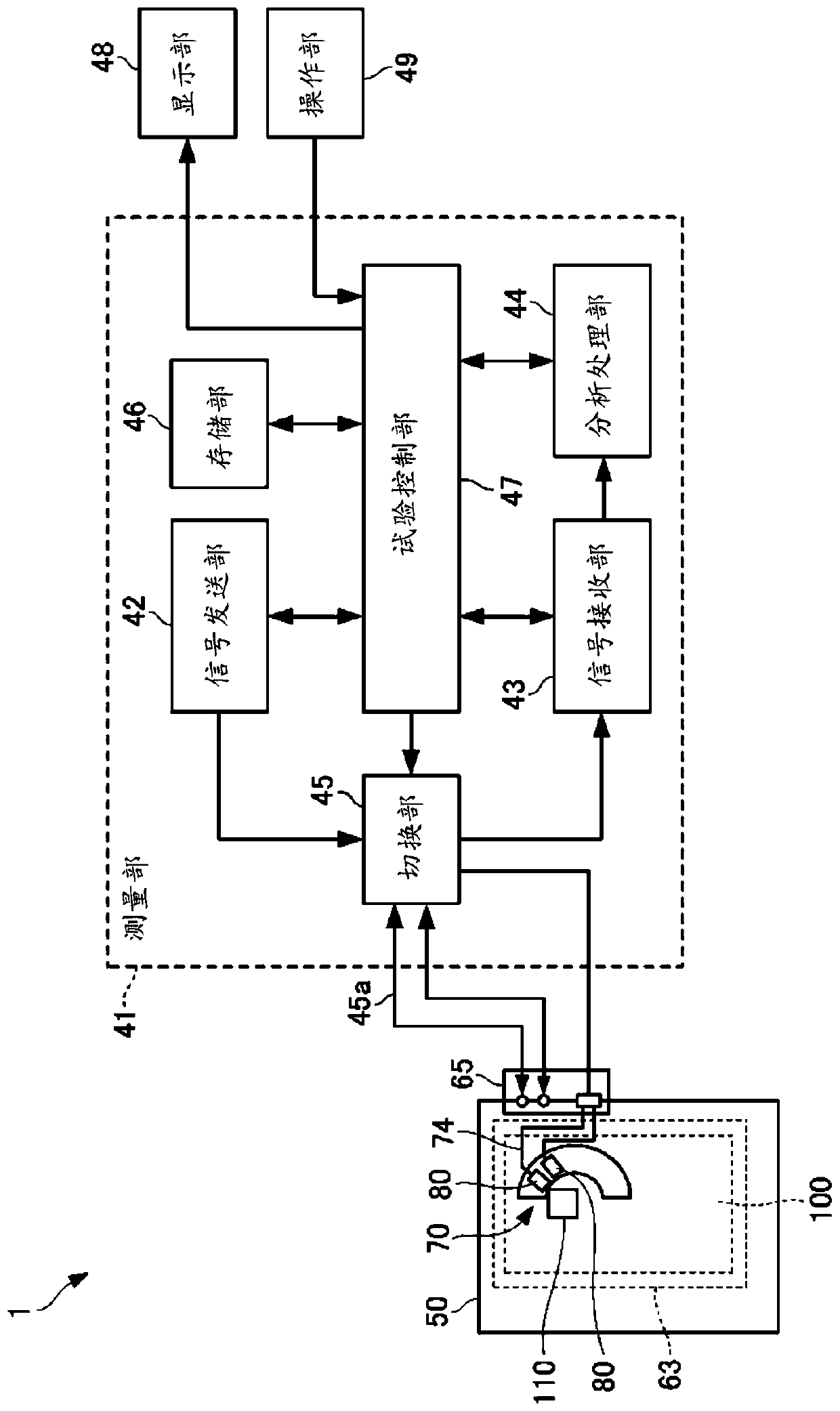
[0061] like figure 1 As shown, wireless terminal measuring device 1 according to an embodiment of the present invention inputs test signals to DUT 100 having one or more antennas 110 , and performs measurement (test) of transmission and reception characteristics and the like on signals to be measured output from DUT 100 . For example, the wireless terminal measurement device 1 includes a measurement unit 41 , a display unit 48 , an operation unit 49 , and an electromagnetic wave shielding box 50 .

[0062] DUT100 is wireless terminals, such as a smartphone, for example. Examples of communication standards for the DUT 100 include cellular (LTE, LTE-A, W-CDMA (registered trademark), GSM (registered trademark), CDMA2000, 1xEV-DO, TD-SCDMA, etc.), wireless LAN (IE...


PUM


Abstract

An electromagnetic wave shield box (50) accommodates a DUT (100) having an antenna (110) and a coupling antenna 80 that is spatially coupled to the antenna (110), and includes a coupling antenna holding module (70) that arranges a plurality of the coupling antennas (80) annually so that an antenna surface is directed to a center of a ring, and holds the coupling antennas (80). The coupling antennaholding module (70) holds each coupling antenna (80) in a posture in which the coupling antenna (80) is inclined at, for example, 32 degrees with respect to a horizontal surface so that the respective coupling antennas (80) are able to radiate radio waves toward the same radiation point in upper positions, and is rotated by about 5 degrees around a center axis (C1) in a direction orthogonal to acircumferential direction of the ring of the coupling antenna (80).

Description

technical field [0001] The present invention relates to an electromagnetic wave shielding box for accommodating a test object having an antenna and a coupling antenna spatially coupled to the antenna so as to block electromagnetic waves from the outside. Background technique [0002] In recent years, with the development of multimedia, wireless terminals (smart phones, etc.) equipped with antennas for wireless communication such as cellular and wireless LAN have been mass-produced. In the future, wireless terminals that transmit and receive wireless signals corresponding to IEEE802.11ad and 5G cellular, etc., that use wideband signals in the millimeter wave band will be particularly demanded. [0003] In a wireless terminal manufacturing factory, a wireless communication antenna included in a wireless terminal measures the output level of a transmission radio wave or the receiving sensitivity specified in each communication standard, and conducts a performance test to determ...

Claims


Application Information

Patent Timeline
IPC IPC(8): H05K9/00H04W24/08
CPCH04W24/08H05K9/006H01Q1/526H05K9/0069H04B17/15H01Q1/243H01Q1/38H01Q9/0428H04B17/20
Inventor 古藤穰治丸尾友彦森田智纪
Owner ANRITSU CORP
Learn More