
A kind of tunneling field effect transistor and its preparation method

A tunneling field effect, transistor technology, applied in semiconductor/solid-state device manufacturing, diodes, semiconductor devices, etc., can solve the problems of bipolar parasitic current and low on-state drive current, improve on-state drive current, suppress dual Extreme parasitic current phenomenon, effect of improving subthreshold slope

Active Publication Date: 2021-05-04
SHANGHAI INST OF MICROSYSTEM & INFORMATION TECH CHINESE ACAD OF SCI
View PDF5 Cites 0 Cited by
  • Summary
  • Abstract
  • Description
  • Claims
  • Application Information

AI Technical Summary

Problems solved by technology

[0005] In view of the shortcomings of the prior art described above, the purpose of this application is to provide a tunneling field effect transistor and its preparation method, which are used to solve the problem of bipolar parasitic currents and on-state driving of tunneling field effect transistors in the prior art. low current problems

Method used


Image

  • A kind of tunneling field effect transistor and its preparation method
  • A kind of tunneling field effect transistor and its preparation method
  • A kind of tunneling field effect transistor and its preparation method

Examples


Embodiment Construction

[0048] The following will clearly and completely describe the technical solutions in the embodiments of the present invention with reference to the drawings in the embodiments of the present invention. Apparently, the described embodiments are only some of the embodiments of the present invention, but not all of them. Based on the embodiments of the present invention, all other embodiments obtained by persons of ordinary skill in the art without making creative efforts belong to the protection scope of the present invention.

[0049]Reference herein to "one embodiment" or "an embodiment" refers to a particular feature, structure or characteristic that can be included in at least one implementation of the present invention. In the description of the present invention, it should be understood that the orientation or positional relationship indicated by the terms "upper", "lower", "top", "bottom" etc. is based on the orientation or positional relationship shown in the drawings, a...


PUM

PropertyMeasurementUnit
thicknessaaaaaaaaaa
thicknessaaaaaaaaaa
thicknessaaaaaaaaaa

Abstract

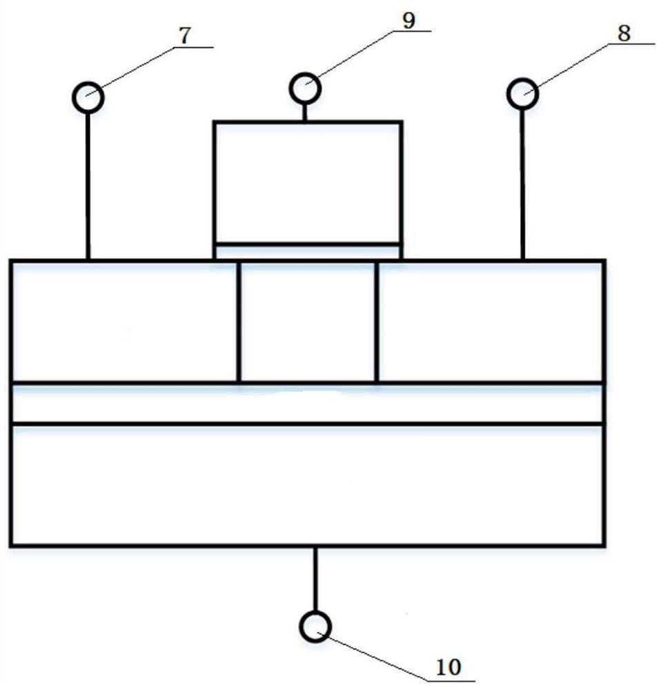
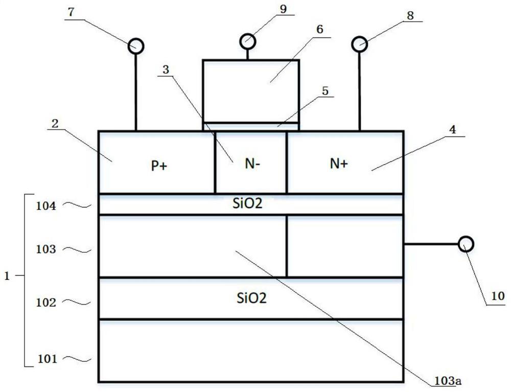
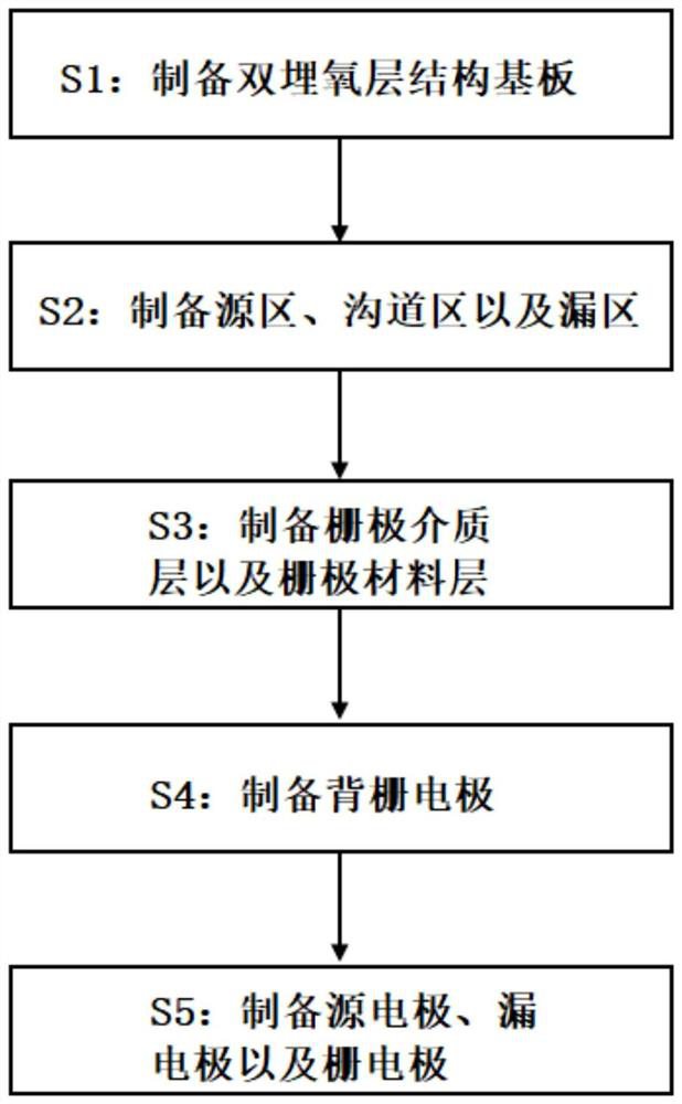
The present application provides a tunneling field effect transistor and a manufacturing method thereof. The tunneling field effect transistor comprises: a double-buried oxide layer structure substrate; the double-buried oxide layer structure substrate includes at least a silicon substrate, a first buried oxide layer An oxygen layer, a silicon material layer and a second buried oxide layer, the silicon material layer is provided with an air cavity; the source region, the channel region and the drain region; the source region, the channel region and the drain region are located on the surface of the second buried oxide layer, and the channel The region is connected between the source region and the drain region, and the positions of the source region and the channel region correspond to the air cavity; the gate dielectric layer and the gate material layer; the gate dielectric layer is at least located on the surface of the channel region, and the gate material layer is located on the The surface of the gate dielectric layer; the source electrode, the drain electrode and the gate electrode; the source electrode is formed on the surface of the source region, the drain electrode is formed on the surface of the drain region, and the gate electrode is formed on the surface of the gate material layer; the back gate electrode; the back gate electrode is formed on the The surface of the silicon material layer, and the position of the back gate electrode corresponds to one side of the drain electrode.

Description

technical field [0001] The invention relates to the technical field of semiconductor devices, in particular to a tunneling field effect transistor and a preparation method thereof. Background technique [0002] In Metal-Oxide-Semiconductor Field-Effect Transistor (MOSFET), carriers are thermally injected from the source across the PN junction barrier into the channel, while Tunneling Field-Effect Transistor (Tunneling Field-Effect Transistor) , TFET) works on the principle of band-to-bandtunneling (BTBT), when the PN junction is in the reverse bias state, when some empty energy states in the conduction band of the N region are not occupied by electrons and the valence band of the P region Some of the energy states occupied by electrons have the same energy, and when the barrier region is very narrow, electrons will tunnel from the valence band of the P region to the conduction band of the N region. Transistors designed using the principle of electron tunneling have the adva...

Claims


Application Information

Patent Timeline
Patent Type & Authority Patents(China)
IPC IPC(8): H01L29/739H01L27/12H01L29/423H01L21/331
CPCH01L27/1207H01L29/42356H01L29/66356H01L29/7391
Inventor 吕凯董业民
Owner SHANGHAI INST OF MICROSYSTEM & INFORMATION TECH CHINESE ACAD OF SCI
Learn More