
Compensation type seal plug valve

A plug valve and compensation technology, applied in the field of plug valves, can solve problems such as seal failure and achieve the effect of increasing the specific pressure of the seal

Pending Publication Date: 2020-02-28
浙江福瑞科流控机械有限公司
View PDF1 Cites 2 Cited by
  • Summary
  • Abstract
  • Description
  • Claims
  • Application Information

AI Technical Summary

Problems solved by technology

[0005] The purpose of the present invention is to provide a compensable sealing plug valve, which has a compensable sealing structure, which can solve the problem of sealing failure caused by wear between the plug and the bush after long-term use, thereby prolonging the life of the plug valve. service life

Method used


Image

  • Compensation type seal plug valve
  • Compensation type seal plug valve
  • Compensation type seal plug valve

Examples


Embodiment 1

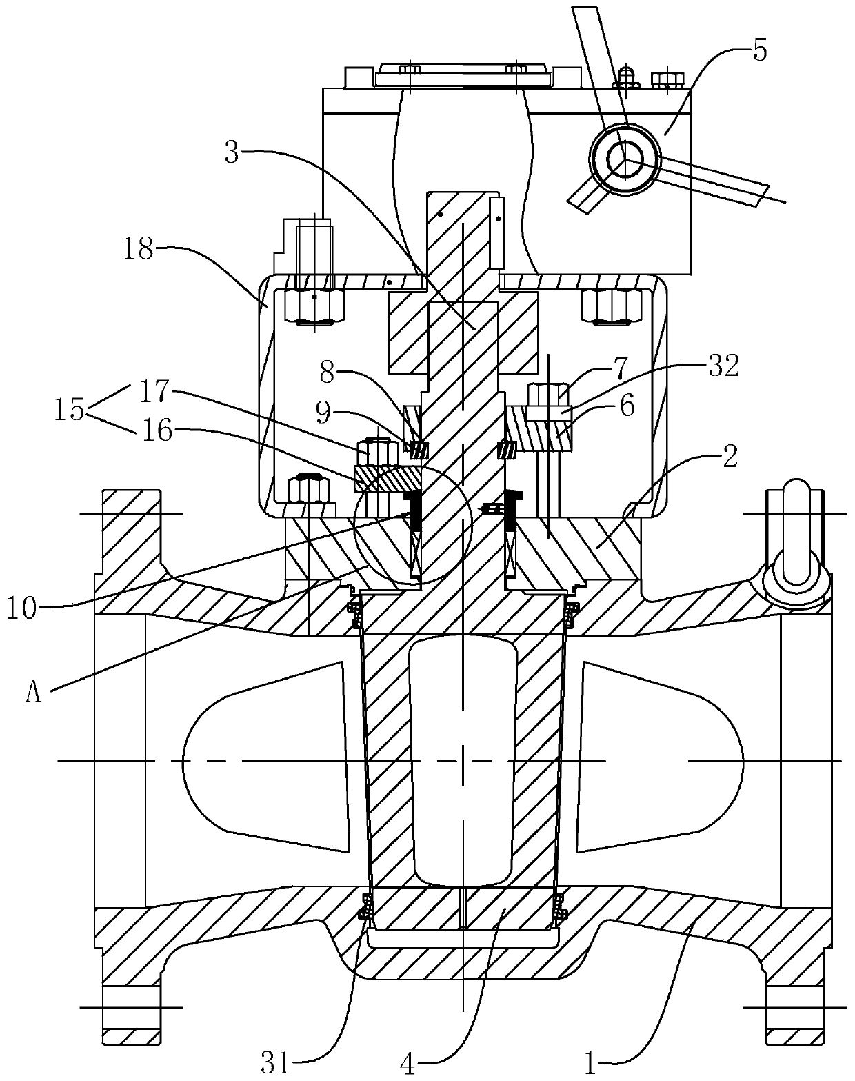
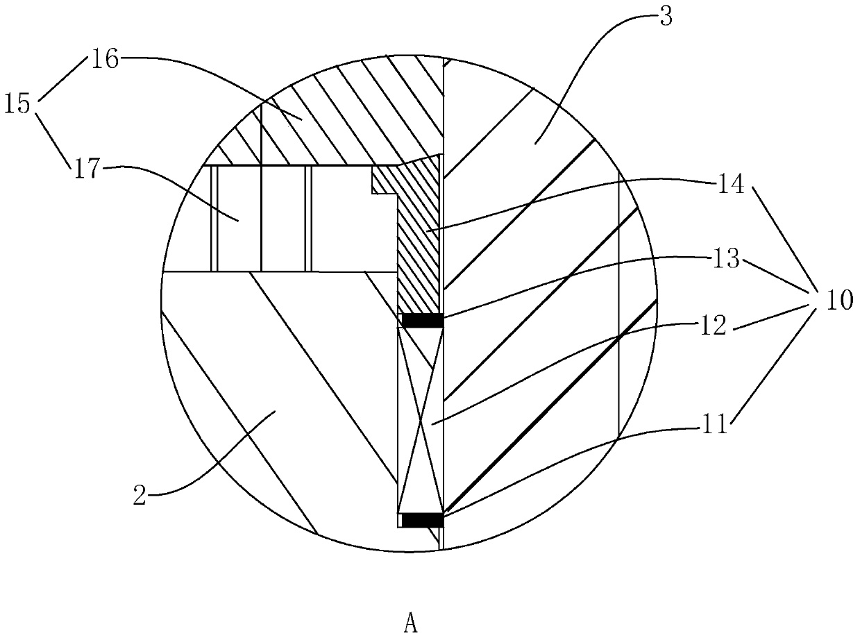
[0025] Such as Figure 1-Figure 2 As shown, a compensable sealing plug valve includes a valve body 1, a valve cover 2 and a valve stem 3. The valve body 1 is provided with a valve cavity communicating with the inlet end and the discharge end, and the valve stem 3 is inside the valve cavity. A plug body 4 is provided at one end of the valve body, and a bushing 31 is provided between the plug body 4 and the valve body.

[0026] The end of the valve stem 3 away from the plug body 4 is key-connected with a driving device 5 capable of driving the valve stem 3 to rotate. One end of the valve stem 3 outside the valve body 1 is provided with an adjusting pressure plate 6 , and one side of the adjusting pressure plate 6 is pierced with a first fastener 7 , and one end of the first fastener 7 is threadedly engaged with the valve cover 2 .

[0027] After long-term use of the plug valve, the sealing surface of the bushing 31 and the plug body 4 will be worn, resulting in an increase in t...

Embodiment 2

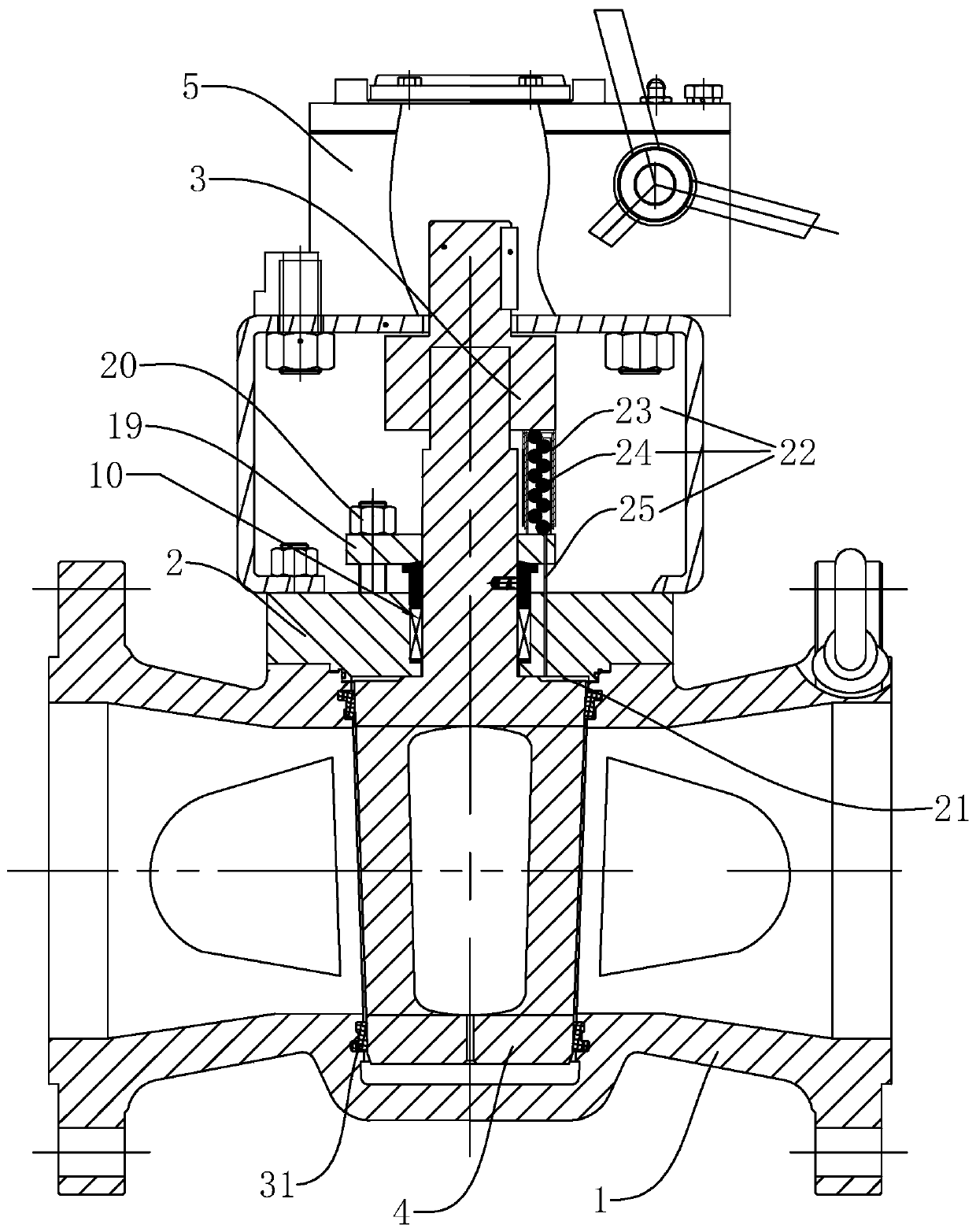
[0039] The difference from the embodiment is: as Figure 3-Figure 5 As shown, one end of the valve stem 3 outside the valve body 1 is fixedly connected with a sealing compensation pressure plate 19 , and the bottom of the sealing compensation pressure plate 19 is in contact with the upper surface of the sealing packing assembly 10 . One side of the sealing compensating pressure plate 19 is pierced with a third fastener 20 , and one end of the third fastener 20 is screwed into the valve cover 2 .

[0040] By setting the sealing compensation pressure plate 19 and the third fastener 20 above, when one end of the third fastener 20 is screwed into the valve cover 2 to reduce the distance between the sealing compensation pressure plate 19 and the valve cover 2 . It can synchronously drive the valve stem 3 and the plug body 4 at one end of the valve stem 3 to move towards the bushing 31 to increase the sealing contact surface between the plug body 4 and the bushing 31 and increase th...


PUM


Abstract

The invention discloses a compensation type seal plug valve. The compensation type seal plug valve comprises a valve body, a valve cover and a valve rod. A valve cavity communicating with an inlet endand a discharging end is formed in the valve body, the end, in the valve cavity, of the valve rod is provided with a plug body, a bush is arranged between the plug body and the valve body, the crosssectional area of the end, away from the valve rod, of the plug body is smaller than that of the end, close to the valve rod, of the plug body, the end, away from the plug body, of the valve rod is inkey connection with a driving device capable of driving the valve rod to rotate, the end, outside the valve body, of the valve rod is provided with an adjusting pressing plate, one side of the adjusting pressing plate is provided with a first fastener in a penetrating manner, and one end of the first fastener is in threaded fit with the valve cover. The plug valve has the advantages that the plugvalve has the compensation type seal structure, the seal failure caused by wear between the plug and the bush after long-time use can be solved, and the service life of the plug valve is prolonged.

Description

technical field [0001] The invention relates to a plug valve, in particular to a compensable sealing plug valve. Background technique [0002] The plug valve is a closing member or a plunger-shaped rotary valve. By rotating 90 degrees, the channel port on the valve plug communicates with or separates from the channel port on the valve body to realize opening or closing. The shape of its valve plug can be cylindrical or conical, and the channel is trapezoidal. [0003] The Chinese patent with the notification number CN204961883U discloses a cock valve, which includes a valve body, a cock and a valve cover. The valve body is provided with a valve cavity, the cock is located in the valve cavity, and the top of the cock is connected with a cock rod. The valve body is made of alloy steel, the cock is made of ceramics, the cock and the valve body are fitted with a cylinder, the contact surface between the cock and the valve body is provided with a rotating bushing, and the rotati...

Claims


Application Information

Patent Timeline
Patent Type & Authority Applications(China)
IPC IPC(8): F16K5/02F16K5/16F16K5/08F16K41/02
CPCF16K5/0207F16K5/0285F16K5/08F16K5/161
Inventor 郑建军李泽玉张浩郑坤明林利平张阳秀王志明
Owner 浙江福瑞科流控机械有限公司
Learn More