Skin pore recognition and positioning depilation system based on computer vision

A computer vision, identification and positioning technology, applied in the field of skin pore identification, positioning and hair removal systems, can solve problems such as hidden dangers of laser safety, complex system of the whole machine, unadjustable light spot of the treatment handle, etc., and achieves the effect of reducing the load level and reducing the power requirement.

Inactive Publication Date: 2020-02-28
广州三土医疗科技有限公司
View PDF6 Cites 4 Cited by
  • Summary
  • Abstract
  • Description
  • Claims
  • Application Information

AI Technical Summary

Problems solved by technology

[0003] The power of the traditional high-power semiconductor laser used in this equipment is often between 300-2400W, and the laser generated has potential safety hazards, and the higher the laser power, the greater the heat generation, and the system must use a higher-power cooler to run stably. At the same time, the structure of the treatment handle is complex, and the high-power laser used is expensive, the light spot of the treatment handle cannot be adjusted, and the whole system is complicated

Method used


Image

  • Skin pore recognition and positioning depilation system based on computer vision
  • Skin pore recognition and positioning depilation system based on computer vision
  • Skin pore recognition and positioning depilation system based on computer vision

Examples


Embodiment 1

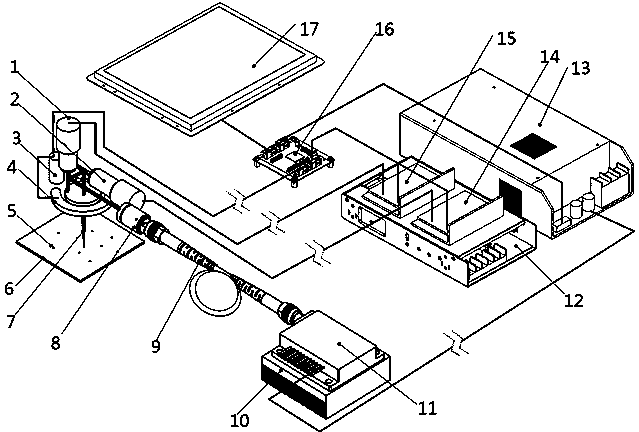
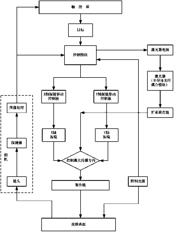
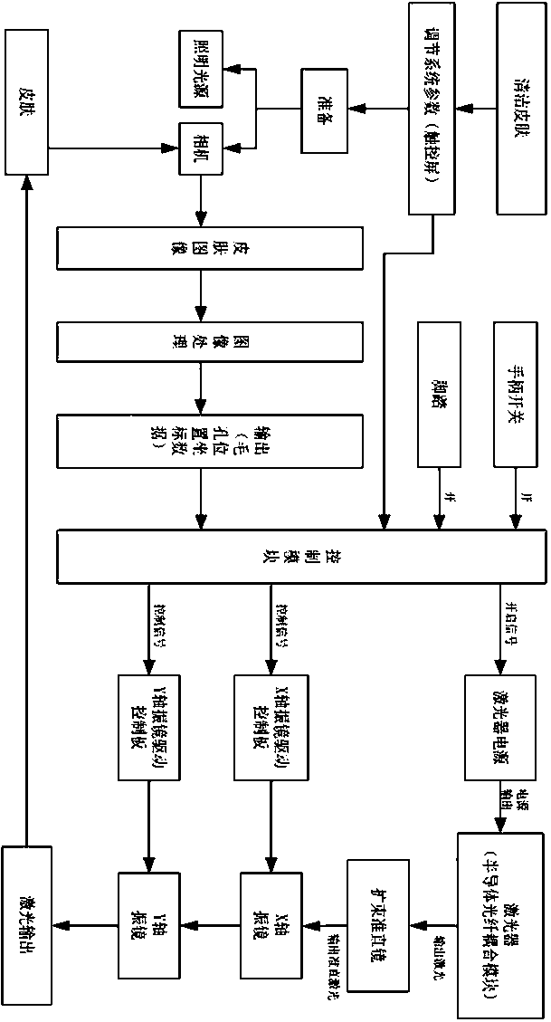
[0031] see Figure 1~3 ,, in an embodiment of the present invention, a skin pore recognition and positioning hair removal system based on computer vision includes a host system and a treatment handle, the host system includes a display system, a control system and a power system, and the power system includes a switching power supply 12 And laser power supply 13, control system includes X-axis galvanometer drive control board 15, Y-axis galvanometer drive control board 14 and control module 16, display system includes touch screen 17, and described treatment handle includes semiconductor laser coupling module, collimation system, XY scanning galvanometer, focusing mirror, camera image processing module and illumination source 4, the lower part of the illumination source 4 is aimed at the skin 6 and the pores 5 on it, and the camera image processing module is located on one side of the illumination source 4, A camera 3 is provided, the scanning galvanometer is located above the...

Embodiment 2

[0050] On the basis of Embodiment 1, the power supply of the power supply system is independently controlled, so that the laser 11 is powered by the laser power supply 13, and the switching power supply 12 supplies the control module 16, the X-axis vibrating mirror driving control board 15 and the Y-axis vibrating mirror driving control board 14 Power supply to realize the stable power consumption of the control components and ensure the stable operation of the device.


PUM


Abstract

The invention relates to the field of cosmetic medicine, in particular to a skin pore recognition and positioning depilation system based on computer vision, comprising a main unit system and a treatment handle; the main unit system comprises a display system, a control system and a power supply system; the treatment handle comprises a semiconductor laser coupling module, a collimation system, anXY scanning galvanometer, a focusing lens, a camera image processing module and an illumination light source; the machine vision image-processing technology is applied to the field of semiconductor laser depilation, the traditional high-power semiconductor laser depilation is broken through, and depilation is carried out by means of the low-power semiconductor laser fiber coupling module; after animage is collected by a camera, sending the image to a PC (personal computer) for image processing is not required; after the image is collected by the camera, digital image processing is carried outthrough hardware (FPGA, DSP, and DSP+FPGA), pore position data are directly output; the machine vision intelligent identification technology is integrated, and targeted treatment can be carried out on skin, so that the power requirement of a laser is greatly lowered; the area of a treatment region is adjustable, so that the loading degree of the whole machine system is greatly reduced.

Description

technical field [0001] The invention relates to the field of medical aesthetics, in particular to a computer vision-based skin pore recognition and positioning hair removal system. Background technique [0002] Laser medical cosmetology is an important branch of medicine, and it is developing rapidly. Laser hair removal is also an important part of laser medical cosmetology. The semiconductor laser hair removal treatment device is currently the main treatment device that can achieve human hair removal. It can achieve permanent and painless hair removal, and it is safe, traceless and convenient. By emitting laser pulses with suitable wavelength range and energy to generate heat to destroy hair follicles, the purpose of laser hair removal is achieved. Machine vision and visual detection and analysis of skin images have potential application value in the professional medical and beauty fields. In machine vision image processing to assist skin analysis, skin pores are more effe...

Claims


Application Information

Patent Timeline
IPC IPC(8): A61B18/22A61B90/11G16H40/63
CPCA61B18/22A61B90/11A61B2018/00476G16H40/63
Inventor 杨国锋王垚
Owner 广州三土医疗科技有限公司
Why Eureka
Try Eureka