
An Optical Measuring Device for Measuring Gas Parameters in Combustion Fields

A technology of gas parameter measurement and optical measurement, which is applied in the direction of measuring device, color/spectral characteristic measurement, material analysis through optical means, etc. It can solve the problems of poor measurement results and insufficient number of light layouts, etc., and achieve high strength and compact structure , good stability

Active Publication Date: 2021-01-01
PLA PEOPLES LIBERATION ARMY OF CHINA STRATEGIC SUPPORT FORCE AEROSPACE ENG UNIV
View PDF5 Cites 0 Cited by
  • Summary
  • Abstract
  • Description
  • Claims
  • Application Information

AI Technical Summary

Problems solved by technology

[0003] The invention provides an optical measuring device for measuring gas parameters in a combustion field, which can solve the problem of poor measurement results caused by insufficient light distribution in the flow field in the prior art

Method used


Image

  • An Optical Measuring Device for Measuring Gas Parameters in Combustion Fields
  • An Optical Measuring Device for Measuring Gas Parameters in Combustion Fields
  • An Optical Measuring Device for Measuring Gas Parameters in Combustion Fields

Examples


Embodiment Construction

[0043]The present invention will be described in detail below in conjunction with examples, but the present invention is not limited to these examples.

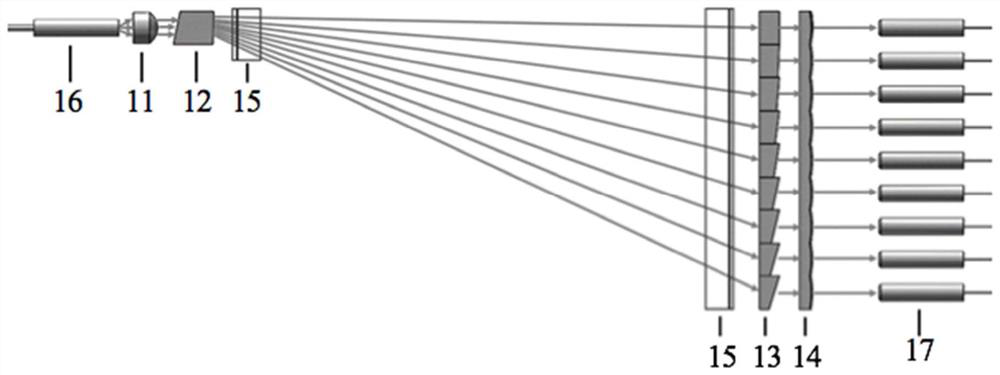
[0044]The embodiment of the present invention provides an optical measurement device for measuring gas parameters of a combustion field, such asfigure 1 As shown, the optical measurement device includes a laser emitting module and a laser receiving module located on opposite sides of the flow field; the laser emitting module includes a collimating unit 11 and a light shape conversion unit 12 arranged on the light exit side of the collimating unit 11; The unit 11 is used to convert the incident laser beam into a collimated beam; the light shape conversion unit 12 is used to convert the collimated beam into a fan-shaped surface light source; the laser receiving module includes a deflection unit 13 arranged in the irradiation area of ​​the fan-shaped surface light source, and The focusing unit 14 on the light exit side of the deflection ...


PUM


Abstract

The invention discloses an optical measuring device for combustion field gas parameter measurement, belongs to the technical field of flow field optician measurement, and aims at solving the problem that the measuring results are relatively bad as the light laying quantities in the flow fields are insufficient in the prior art. The optical measuring device comprises a laser emission module and a laser reception module on two opposite sides of a flow field, wherein the laser emission module comprises a collimation unit and a light form conversion unit on the light-out side of the collimation unit; the collimation unit is used for converting the incident laser into a collimation light beam; the light form conversion unit is used for converting the collimation light beam into a fan-shaped surface light source; the laser reception module comprises a deflection unit which is arranged in an irradiation area of the fan-shaped surface light source and a focusing unit which is arranged on the light-out side of the deflection unit; the deflection unit is used for converting the fan-shaped surface light source into a collimation light ray; and the focusing unit is used for focusing the collimation light ray converted by the deflection unit. The optical measuring device is used for the gas parameter measurement of combustion flow fields.

Description

Technical field[0001]The invention relates to an optical measurement device for measuring gas parameters of a combustion field, belonging to the technical field of flow field optical measurement.Background technique[0002]Tunable Diode Laser Absorption Tomography (TDLAT, Tunable Diode Laser Absorption Tomography) is a fusion technology of laser absorption spectroscopy technology and computational imaging technology. It uses gas molecules to absorb light and computational imaging to achieve a tomographic two-dimensional gas flow field. reconstruction. In the prior art, when using TDLAT technology to measure the combustion flow field of an engine, an orthogonal distributed light layout scheme is usually adopted, that is, multiple corresponding laser emitting units and multiple laser receiving units are set, and each laser emitting unit emits After the laser passes through the flow field to be measured, it is received by the corresponding laser receiving unit. However, due to the limite...

Claims


Application Information

Patent Timeline
Patent Type & Authority Patents(China)
IPC IPC(8): G01N21/39G01N21/01
CPCG01N21/01G01N21/39G01N2021/0112G01N2021/394
Inventor 洪延姬宋俊玲辛明原饶伟冯高平赵文涛娄登程姜雅晶叶继飞李南雷周伟静
Owner PLA PEOPLES LIBERATION ARMY OF CHINA STRATEGIC SUPPORT FORCE AEROSPACE ENG UNIV
Learn More