Hazardous waste sludge separation type treatment device

A treatment device and sludge treatment technology, applied in sludge treatment, water/sludge/sewage treatment, neutralized water/sewage treatment, etc., can solve the problem of automatic adjustment of mixing methods, hazardous waste combustion, damage to mixing mechanisms, etc. problem, achieve the effect of reducing the risk of combustion and explosion, reducing metal ions, and avoiding corrosion

Inactive Publication Date: 2020-02-25
徐州鸿誉环境科技有限公司
View PDF1 Cites 3 Cited by
  • Summary
  • Abstract
  • Description
  • Claims
  • Application Information

AI Technical Summary

Problems solved by technology

It is difficult for traditional mixers to automatically adjust the mixing method according to the water content of hazardous waste. If the auxiliary method of liquid mixing is used, it is easy to cause combustion or even explosion of hazardous waste, as well as damage to the mixing mechanism.
[0003] Chinese patent (authorized announcement number: CN209507940U) discloses a hazardous waste sludge treatment mixer, a hazardous waste sludge treatment mixer, through the improvement of the stirring mechanism, and the use of humidity sensors, vibration exciters and temperature detection mechanisms, The mixer can automatically adjust the mixing according to the water content of hazardous waste; however, there are some practical defects in this patent. The patent does not disclose the principle of effective detection of water quality, nor does it give a specific treatment method

Method used


Image

  • Hazardous waste sludge separation type treatment device
  • Hazardous waste sludge separation type treatment device
  • Hazardous waste sludge separation type treatment device

Examples


Embodiment 1

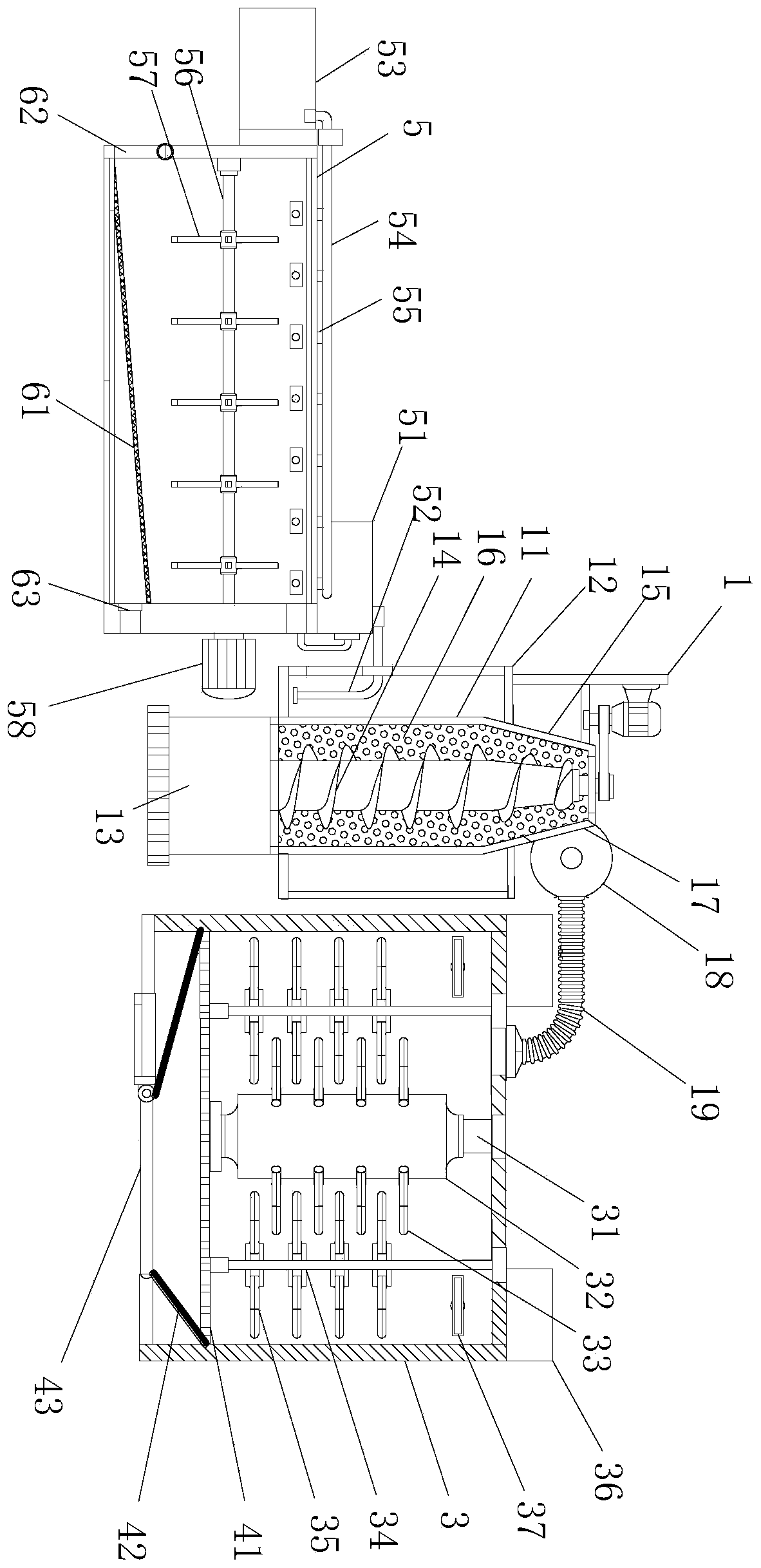
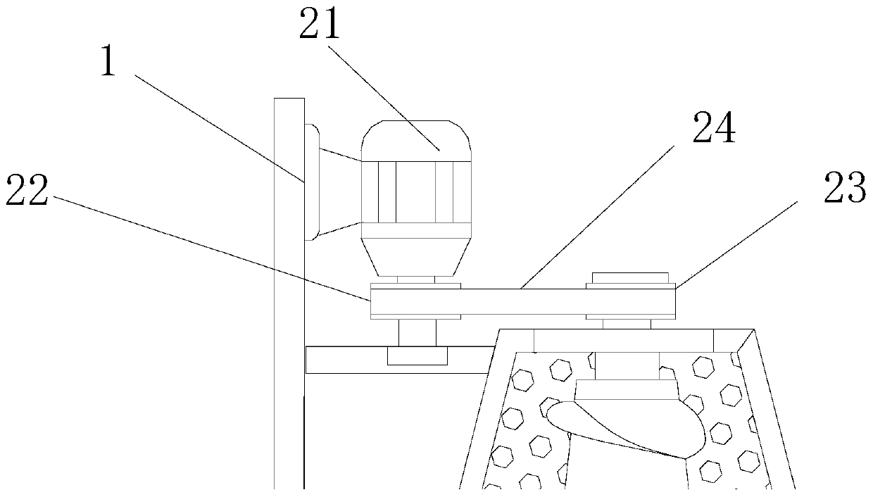
[0030] see Figure 1~3 , a hazardous waste sludge separation treatment device, comprising a sludge feeder 1, a sludge treatment tank 3 and a sewage treatment tank 5, the sludge feeder 1 is provided with a feeder 11 and a water tank 12. The water storage tank 12 is wrapped and installed on the outer layer of the feeding tube 11, the bottom end of the feeding tube 11 is installed with a dredge pump joint 13, and the outer wall of the feeding tube 11 is provided with several water outlet holes 16. The auger 14 is installed inside the feeding tube 11, and the top of the feeding tube 11 is provided with a discharge end 15, and the discharge end 15 is provided with a conical structure, and the inner diameter of the tube wall is gradually shrinking. The top side of the discharge end 15 is provided with a discharge port 17, the discharge port 17 is equipped with a feed pump 18, and the discharge end of the feed pump 18 is connected with a sludge conduit 19, the sludge The mud conduit...

Embodiment 2

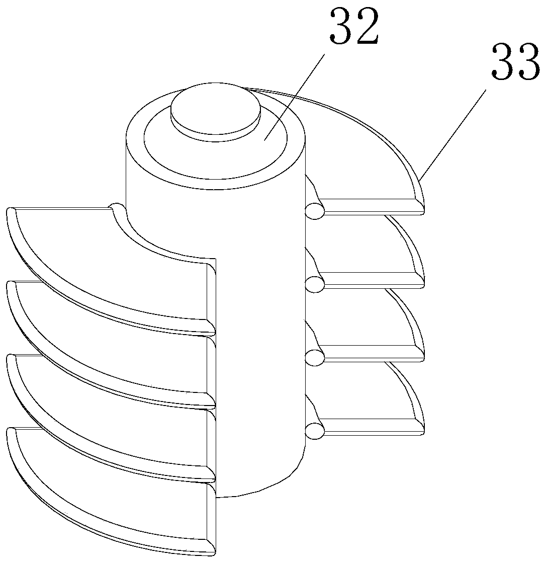
[0034] see figure 1 and image 3, this embodiment is a further optimization of Embodiment 1, on the basis of which, several sludge auxiliary material boxes 36 are arranged on the top of the sludge treatment box 3, and the feeding end of the auxiliary material box 36 extends into the sludge treatment The box 3 is also provided with a material delivery port 37. The sludge treatment box 3 is equipped with a main mandrel 31, and a driving roller 32 is installed on the main mandrel 31. Several A central shaft knife plate 33, the side of the sludge treatment box 3 is provided with several side rollers 34, and several side knife plates 35 are installed on the side roller shaft 34, and the central shaft knife plate 33 and side blade 35 are arranged in a staggered shape.

[0035] For sludge treatment operations, this application pretreats sludge by mixing auxiliary materials. The auxiliary materials mainly use potassium tripolyphosphate-based metal removal materials, hydrated zinc bo...

Embodiment 3

[0040] see figure 1 In this embodiment, as a further optimization of Embodiment 1, on the basis, a sewage auxiliary material box 53 is installed on the side of the sewage treatment tank 5, and a material delivery conduit 54 is installed at the feeding end of the sewage auxiliary material box 53, The feeding conduit 54 is connected to the sewage treatment tank 5 through several branch pipes 55. The inner cavity of the sewage treatment tank 5 is horizontally equipped with a stirring shaft 56, and several stirring rods 57 are installed on the stirring shaft 56. The sewage treatment tank 5 is externally installed with a stirring motor 58, and the stirring shaft 56 is connected with the driving end of the stirring motor 58 through a coupling.

[0041] This application uses acid-base neutralization treatment and adopts the method of stirring operation to improve the mixing of neutralizer and sewage water quality, so as to carry out acid-base pretreatment on the separated sewage, whi...


PUM


Abstract

The invention relates to the related field of environmental protection, and concretely relates to a hazardous waste sludge separation type treatment device. The device comprises a sludge conveying frame, a sludge treatment box and a sewage treatment box, a conveying cylinder and a water accumulation tank are arranged on the sludge material conveying frame, the water accumulation tank is mounted onthe outer layer of the conveying cylinder in a wrapping manner, a dredge pump joint is mounted at the bottom end of the conveying cylinder, a plurality of water outlet holes are formed in the outer wall of the conveying cylinder, a spiral auger is installed in the conveying cylinder, a discharging end is arranged at the top of the conveying cylinder, a conical structure is arranged at the discharging end, the inner diameter of the cylinder wall of the conical structure is gradually reduced, a discharging port is arranged at the side edge of the top of the discharging end, and a conveying pumpis mounted at the discharging port. The device firstly separates a water liquid from the sludge, and then separately treats the water liquid and the sludge, so that the flammable and combustible risks of the hazardous waste sludge are avoided.

Description

technical field [0001] The invention relates to the field of environmental protection, in particular to a hazardous waste sludge separation treatment device. Background technique [0002] Hazardous waste refers to solid and liquid waste with one or more hazardous characteristics such as corrosiveness, toxicity, flammability, reactivity or infectivity. Generally include: waste acid and alkali waste, metals, organics, residues, etc. Hazardous waste is a type of waste that is relatively difficult to dispose of. It is difficult for traditional mixers to automatically adjust the mixing method according to the water content of hazardous waste. If liquid mixing is used for assistance, hazardous waste may burn or even explode, and the mixing mechanism may be damaged. [0003] Chinese patent (authorized announcement number: CN209507940U) discloses a hazardous waste sludge treatment mixer, a hazardous waste sludge treatment mixer, through the improvement of the stirring mechanism, an...

Claims


Application Information

Patent Timeline
Patent Type & Authority Applications(China)
IPC IPC(8): C02F11/122C02F11/148C02F11/00C02F9/04
CPCC02F1/001C02F1/66C02F9/00C02F11/00C02F11/122C02F11/148C02F2001/007
Inventor 刘兆东
Owner 徐州鸿誉环境科技有限公司
Why Eureka
Try Eureka