
Self-tightening type cloth winding device according to winding cycle

A fabric rolling and looping technology, applied in the field of fabric winding, can solve the problems of loose fabrics, the winding device does not have a winding size adjustment mechanism, and the winding speed is slow, and the effect of ensuring the winding speed is achieved.

Inactive Publication Date: 2020-02-25
绍兴市德帏纺织科技有限公司
View PDF8 Cites 0 Cited by
  • Summary
  • Abstract
  • Description
  • Claims
  • Application Information

AI Technical Summary

Problems solved by technology

[0004] However, the traditional winding device can only increase the force of the cloth winding on the surface of the roller by increasing the tension between the cloth and the roller, and this tension must be controlled within a certain range, and while controlling the tension, for To prevent the fabric after winding from being loose, wrinkles often appear on the surface, and the winding speed will slow down. Therefore, this winding method will reduce work efficiency in the process of large-scale fabric production; in addition, the existing The winding device does not have a flexible winding size adjustment mechanism, resulting in only one thickness or diameter of cloth being wound, so a self-tightening cloth winding device based on the number of winding turns came into being.

Method used


Image

  • Self-tightening type cloth winding device according to winding cycle
  • Self-tightening type cloth winding device according to winding cycle
  • Self-tightening type cloth winding device according to winding cycle

Examples


Embodiment Construction

[0022] The following will clearly and completely describe the technical solutions in the embodiments of the present invention with reference to the accompanying drawings in the embodiments of the present invention. Obviously, the described embodiments are only some, not all, embodiments of the present invention. Based on the embodiments of the present invention, all other embodiments obtained by persons of ordinary skill in the art without making creative efforts belong to the protection scope of the present invention.

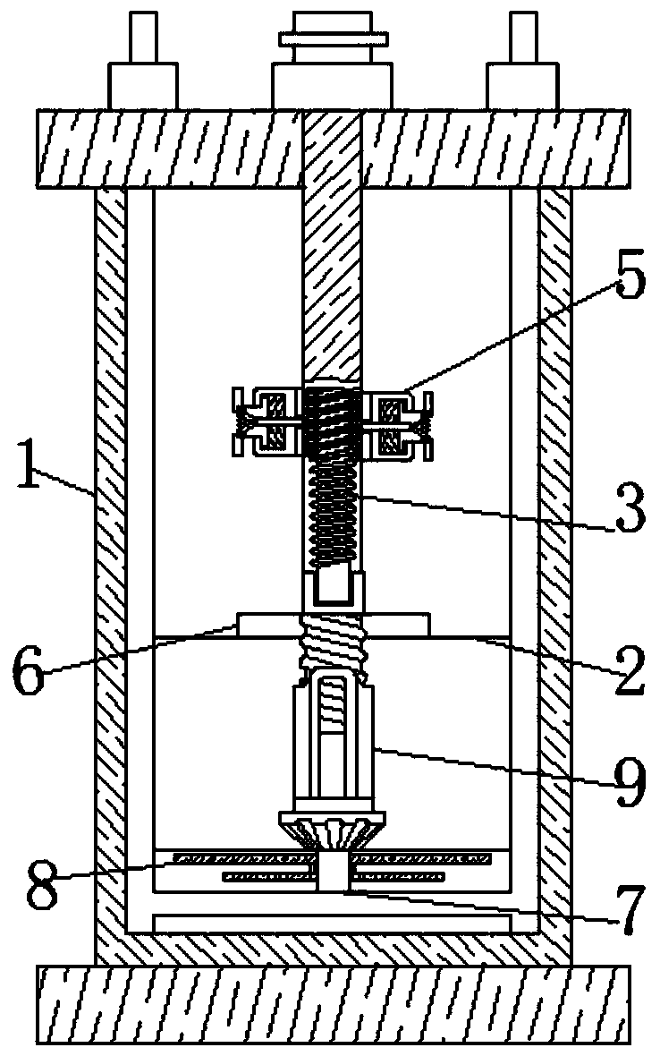
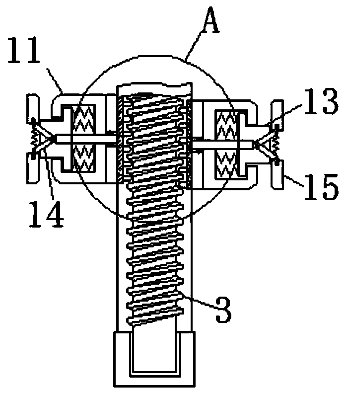
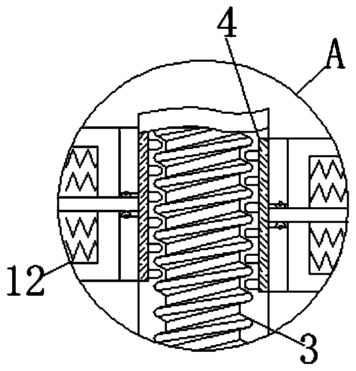
[0023] see Figure 1-5 , a self-tightening cloth winding device according to the number of winding turns, comprising a support frame 1, the inner bottom wall of the support frame 1 is fixedly connected with a base 2, the surface of the base 2 is movably connected with a rotating shaft 3, and the surface of the rotating shaft 3 is movable A shaft sleeve 4 is connected, and the surface of the shaft sleeve 4 is movably connected with an adjustment member 5, and t...


PUM


Abstract

The invention relates to the technical field of cloth winding, and discloses a self-tightening type cloth winding device according to a winding cycle. The device comprises a supporting frame, a base is fixedly connected to the bottom wall in the supporting frame, the surface of the base is movably connected with a rotating shaft, the surface of the rotating shaft is movably connected with a shaftsleeve, the surface of the shaft sleeve is movably connected with an adjusting part, the connecting position of the base and the rotating shaft is sleeved with a flexible plate, a connecting rod is fixedly connected into the base, and the surface of the connecting rod is movably connected with a volute spiral spring. After the rotating shaft rotates by a certain cycle, cloth is wound, at the moment, the volute spiral spring is compressed, when the rotating shaft stops rotating, the compressed force of the volute spiral spring before releasing drives the rotating shaft to rotate in the same direction at the speed larger than the previous rotating speed, cloth wound on the surfaces of the flexible plate and the bearing plate is tightened by the rotating shaft with the speed which is suddenlyaccelerated, and the effect of tightening the cloth while the winding speed is ensured is achieved.

Description

technical field [0001] The invention relates to the technical field of cloth winding, in particular to a self-tightening cloth winding device according to the number of winding turns. Background technique [0002] Cloth is a commonly used material in decoration materials; extensive use of cloth for wall decoration, partition, and background treatment can also form a good commercial space display style. [0003] Cloth is formed through raw materials, spinning, weaving, dyeing and finishing. These processes are indispensable. After processing, the cloth needs to be rolled and packaged to make finished products and put into the market; the traditional cloth winding device is equipped with Rollers wind the fabric around its surface. [0004] However, the traditional winding device can only increase the force of the cloth winding on the surface of the roller by increasing the tension between the cloth and the roller, and this tension must be controlled within a certain range, an...

Claims


Application Information

Patent Timeline
IPC IPC(8): B65H75/24
CPCB65H75/245
Inventor 肖正军
Owner 绍兴市德帏纺织科技有限公司
Learn More