
Rack detecting device and rack detecting method

A detection device and hanger technology, which is applied in the direction of measuring devices, measuring device shells, and measuring electrical variables, etc., can solve the problems of independent detection of multiple chucks that cannot be hanged, and achieve the effect of reducing labor costs and improving efficiency

Pending Publication Date: 2019-06-25
UNIVERSAL CIRCUIT BOARD EQUIP CO LTD
View PDF0 Cites 0 Cited by
  • Summary
  • Abstract
  • Description
  • Claims
  • Application Information

AI Technical Summary

Problems solved by technology

[0004] The object of the present invention is to provide a hanger detection device, aiming to solve the technical problem that the multiple chucks of the hanger cannot be individually detected in the prior art

Method used


Image

  • Rack detecting device and rack detecting method
  • Rack detecting device and rack detecting method
  • Rack detecting device and rack detecting method

Examples


Embodiment Construction

[0039] In order to make the object, technical solution and advantages of the present invention clearer, the present invention will be further described in detail below in conjunction with the accompanying drawings and embodiments. It should be understood that the specific embodiments described here are only used to explain the present invention, not to limit the present invention.

[0040] It should be noted that when an element is referred to as being “fixed on” or “disposed on” another element, it may be directly on the other element or there may be an intervening element at the same time. When an element is referred to as being "connected to" another element, it can be directly connected to the other element or intervening elements may also be present.

[0041] In addition, it should be noted that the orientation terms such as left, right, up, and down in the embodiments of the present invention are only relative concepts or refer to the normal use state of the product, and...


PUM


Abstract

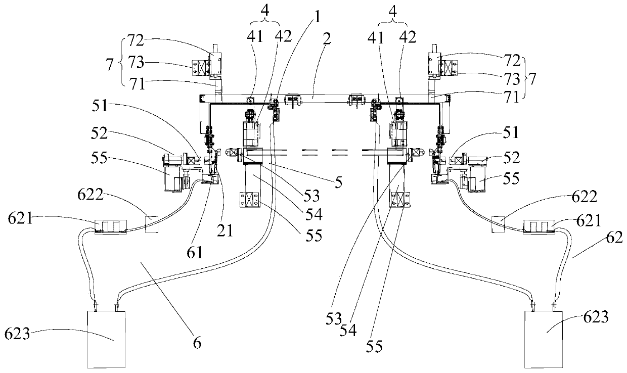
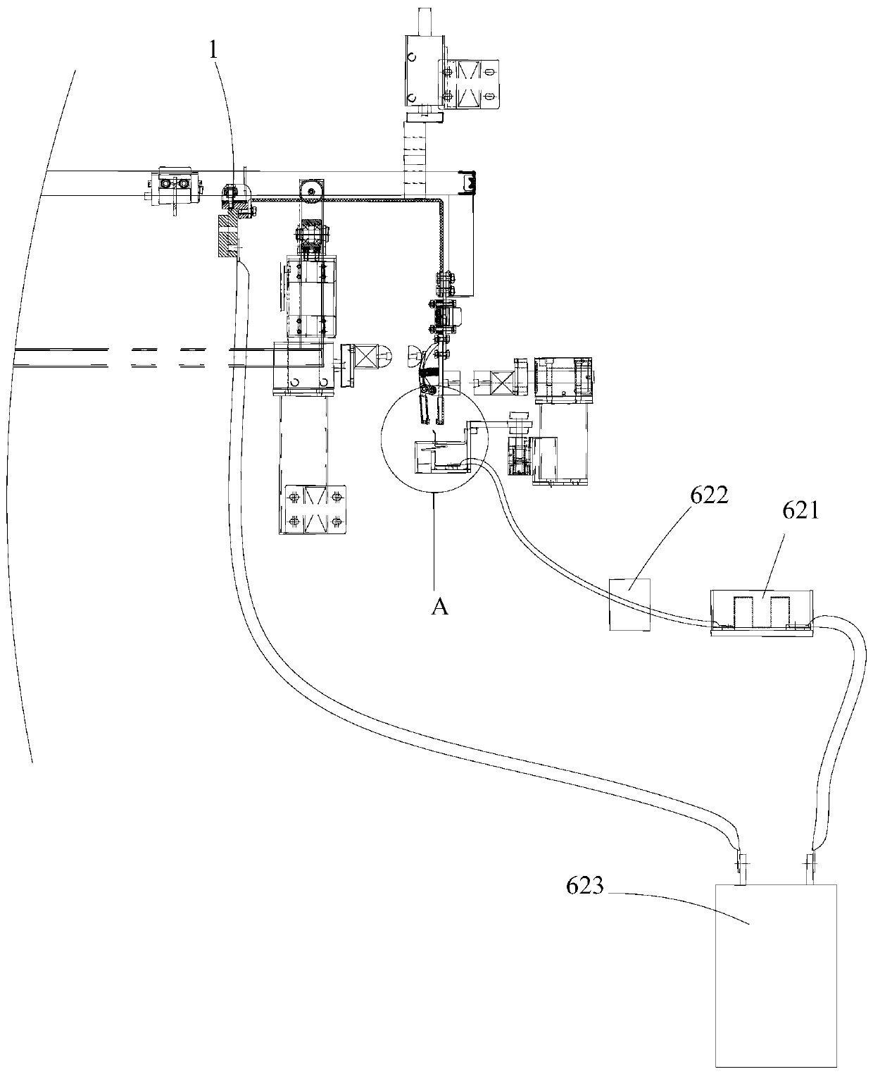
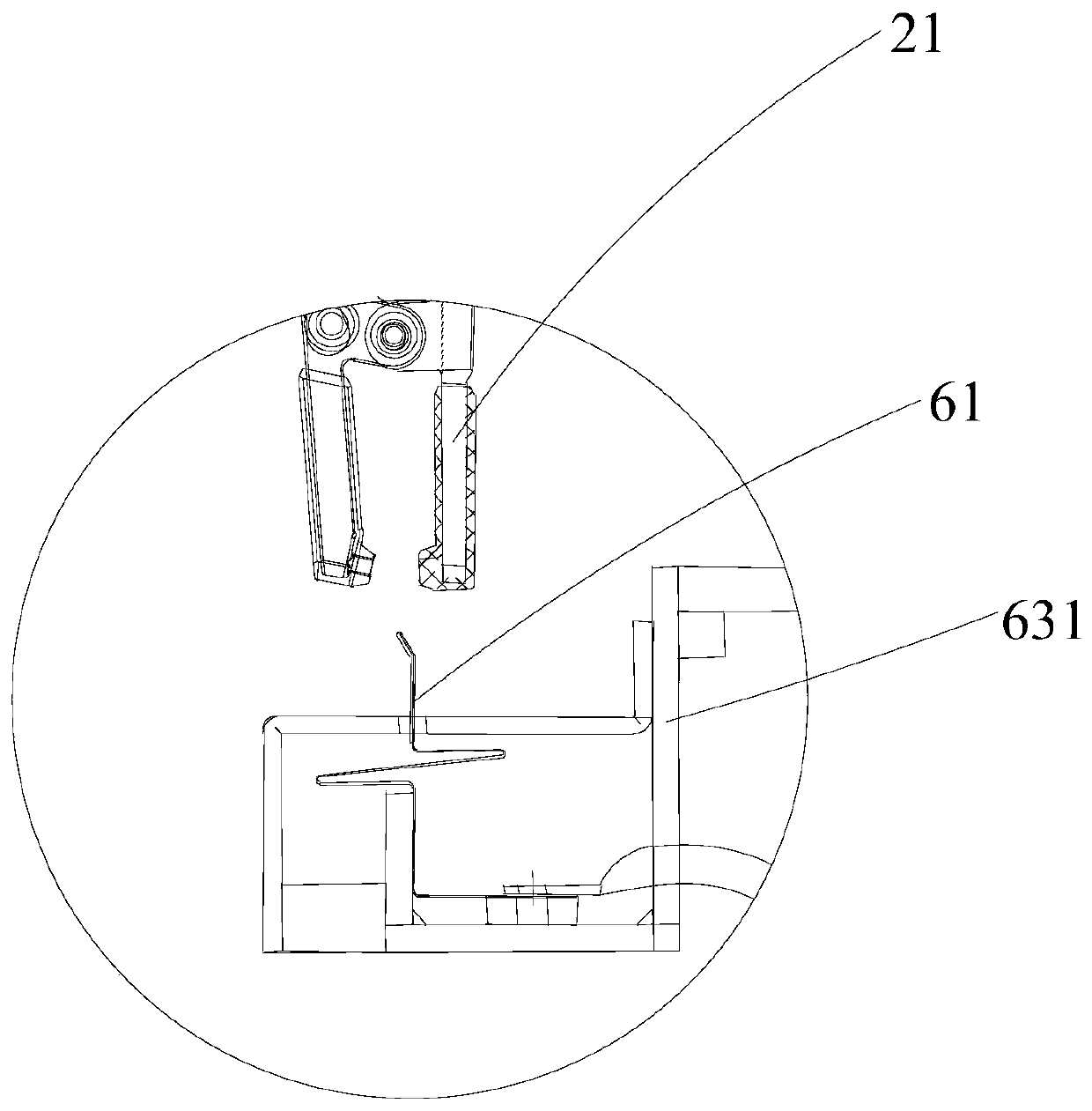
The invention belongs to the technical field of electroplating equipment, and discloses a rack detecting device and a rack detecting method. the rack detecting device comprises a fixing frame, a rackwith multiple conductive chucks, a conveying mechanism, a gear mechanism arranged on the fixing frame for limiting the moving stroke of the rack, a clamping mechanism arranged on the fixing frame to enabling the conductive chuck to perform opening and closing, and a detecting mechanism movably arranged on the fixing frame for detecting and recording the current condition of each conductive chuck.Through arranging the clamping mechanism and the detecting mechanism, the clamping mechanism can open each conductive chuck, the detecting mechanism can extend into the conductive chuck, the clampingmechanism is then separated from the conductive chuck, each conductive chuck clamps the detecting mechanism, the detecting mechanism detects and records the current condition of each conductive chuck,each conductive chuck is detected separately, manual detection of each conductive chuck is avoided, and the manual cost is reduced.

Description

technical field [0001] The invention belongs to the technical field of electroplating equipment, and more specifically relates to a hanger detection device and a hanger detection method. Background technique [0002] The continuous electroplating equipment uses the hanger to move circularly on the circular track, so that the hanger lifts the workpiece (circuit substrate) to be plated by means of propulsion, lifting, etc. for electroplating processing station by station, and then returns to the origin. [0003] Usually, a plurality of chucks for clamping the workpiece to be plated are arranged on the hanger, and the hanger is composed of copper blocks, chucks, wires, contacts, etc., if one of the plurality of chucks When the conductivity is poor, the clamp with poor conductivity has a larger resistance, and the current will choose the path of low resistance, that is, the current flowing through the other clamps will be greater than that of the clamp with poor conductivity. If...

Claims


Application Information

Patent Timeline
Patent Type & Authority Applications(China)
IPC IPC(8): G01R19/00G01R1/04
Inventor 陈德和
Owner UNIVERSAL CIRCUIT BOARD EQUIP CO LTD
Learn More