Forward sound MEMS MIC
A technology of ASIC chip and sound inlet, which is applied in the field of MEMSMIC, can solve the problems of the size limit of the sound cavity of the MEMSMIC, the limitation of the sound pickup performance of the MEMS chip, and the increase of the MEMS chip, so as to improve the sensitivity of the product and the volume of the back sound cavity. The effect of small size and improvement of pickup sensitivity
- Summary
- Abstract
- Description
- Claims
- Application Information
AI Technical Summary
Problems solved by technology
Method used
Image
Examples
Embodiment 1
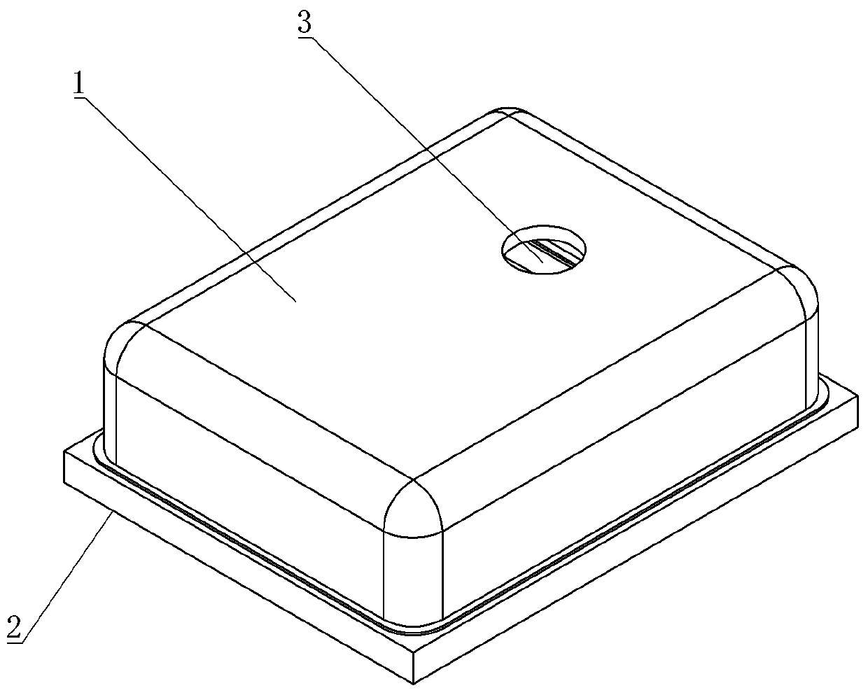
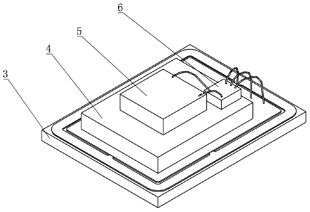
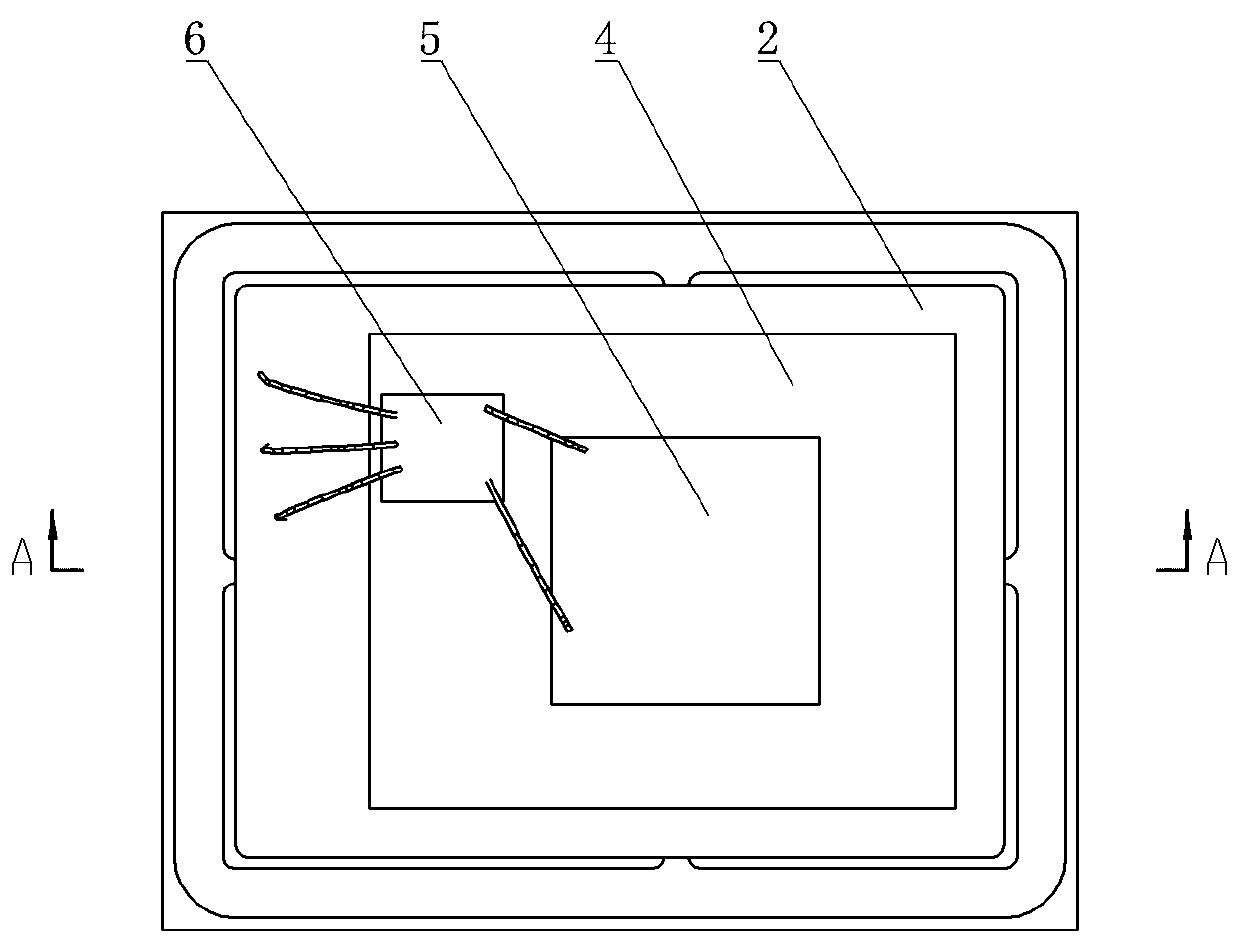
[0023] Embodiment 1: as attached Figures 1 to 6 As shown, a forward sound MEMS MIC includes a sound chamber housing 1, the sound chamber housing 1 is provided with a sound inlet 3, the sound chamber housing 1 is connected with a PCB2, and the sound chamber housing 1 A sound chamber communicating with the sound inlet hole is formed between the PCB2, a MEMS sound pressure sensor chip 5 and an ASIC chip 6 are arranged in the sound chamber, and a rear sound chamber 51 is provided on the MEMS sound pressure sensor chip 5. The PCB2 is provided with a cavity shell 4, and the cavity shell 4 is installed on the PCB2 through traditional welding, bonding, etc., and the MEMS sound pressure sensor chip 5 is installed on the cavity shell 4, and the cavity shell 4 is provided with a cavity 41 , and a cavity 42 communicating with the cavity 41 is formed between the cavity shell 4 and the PCB 2 , and the cavity 41 communicates with the rear sound cavity 51 on the MEMS sound pressure sensor ch...
Embodiment 2
[0028] Embodiment 2: as attached Figure 7 As shown, in this embodiment, the three side walls of the cavity 42 are formed by the sound cavity shell 1 . Specifically, in this embodiment, the cavity shell 4 has a side wall 43, a top wall with a cavity 41 and two legs 45, and the cavity shell 4 is bonded to the PCB 2 through the side wall 43 and the legs 45. The cavity shell 2 closes the remaining side surfaces between the cavity shell 4 and the PCB 2 , forming a cavity 42 with only one cavity 41 communicating with the outside. This structure can further increase the volume of the rear sound cavity, making the volume of the front sound cavity and the rear sound cavity tend to be the same, and achieve better sound pickup effect. Of course, the side walls on any one side or multiple sides of the cavity 42 can be formed by the sound cavity shell.
[0029] The remaining parts in this embodiment are the same as in Embodiment 1.
PUM
 Abstract
Description
Claims
Application Information
 - Generate Ideas
- Intellectual Property
- Life Sciences
- Materials
- Tech Scout
- Unparalleled Data Quality
- Higher Quality Content
- 60% Fewer Hallucinations
Browse by: Latest US Patents, China's latest patents, Technical Efficacy Thesaurus, Application Domain, Technology Topic, Popular Technical Reports.
© 2025 PatSnap. All rights reserved.Legal|Privacy policy|Modern Slavery Act Transparency Statement|Sitemap|About US| Contact US: help@patsnap.com


