
A parallel structure hybrid excitation brushless motor and its power generation system

A hybrid excitation and brushless motor technology, applied to synchronous motors with stationary armatures and rotating magnets, synchronous generators, magnetic circuit shape/style/structure, etc., can solve the problem of reducing system reliability and failing to generate rotating excitation Magnetic field, unable to achieve excitation and other problems, to achieve the effect of reducing capacity

Active Publication Date: 2021-02-09
NANJING UNIV OF AERONAUTICS & ASTRONAUTICS
View PDF5 Cites 0 Cited by
  • Summary
  • Abstract
  • Description
  • Claims
  • Application Information

AI Technical Summary

Problems solved by technology

However, the traditional synchronous reluctance motor, even if a DC field winding is added to the stator, cannot generate a rotating field field that rotates synchronously with the rotor, and excitation cannot be achieved; however, adding a DC field winding to the rotor requires the installation of brushes and Slip rings can provide DC power for DC windings, and armatures and slip rings will inevitably reduce system reliability

Method used


Image

  • A parallel structure hybrid excitation brushless motor and its power generation system
  • A parallel structure hybrid excitation brushless motor and its power generation system
  • A parallel structure hybrid excitation brushless motor and its power generation system

Examples


Embodiment 1

[0066] Embodiment 1 The reluctance rotor is a magnetic barrier rotor

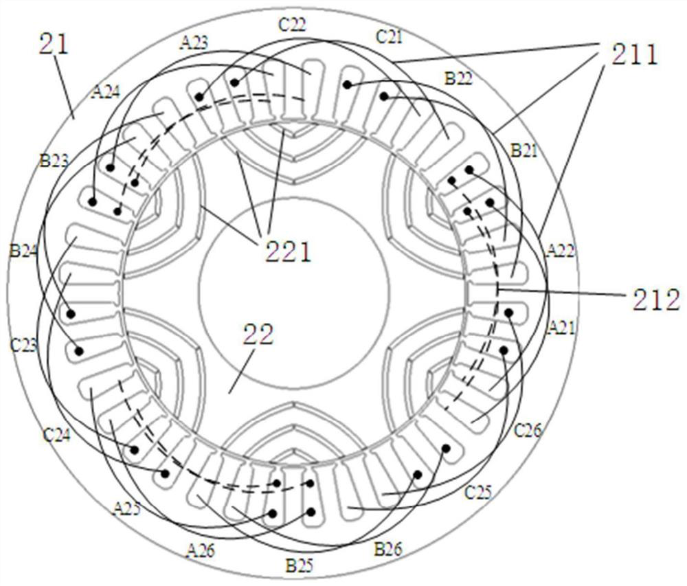
[0067] Such as image 3 As shown, the magnetic barrier rotor includes 2p magnetic barrier groups uniformly distributed along the rotor circumference, and each magnetic barrier group includes one or more than two magnetic barriers 221 stacked. The shape of each layer of magnetic barrier is preferably arc, V-shape or strip, etc., and in this embodiment, it is preferably arc.

[0068] The direct axis is the center line of the two sets of magnetic barriers 221 , the quadrature axis is the center line of the magnetic barriers 221 , and the quadrature axis lags the direct axis by 90 electrical degrees, that is, the lagging mechanical angle is 360 / (4*p).

[0069] further, such as Figure 5 As shown, the magnetic barrier rotor also includes a bar-shaped tangential magnetic barrier 222, and a bar-shaped tangential magnetic barrier arranged in the radial direction is arranged between two adjacent magnetic barrier g...

Embodiment 2

[0070] Embodiment 2 The reluctance rotor is a salient pole rotor

[0071] Such as Image 6 As shown, the direct axis is the center line of the rotor salient pole 223, and the orthogonal axis is the center line of the two salient poles 223 in the salient pole rotor.

Embodiment 3

[0072] Embodiment 3 The reluctance rotor is a mixed pole rotor

[0073] Such as Figure 7 As shown, the reluctance rotor is a hybrid rotor with a mixture of salient poles and magnetic barriers. The hybrid rotor includes 2p salient poles and 2p magnetic barrier groups, and the 2p magnetic barrier groups are arranged in the rotor core between two adjacent salient poles , that is, on the straight axis. The quadrature-axis magnetic barrier is to reduce the reluctance of the quadrature-axis magnetic circuit, and at the same time, it does not affect the direct-axis magnetic circuit: because the direct-axis magnetic circuit is a low reluctance path for the excitation flux, which is conducive to excitation regulation.

[0074] Each magnetic barrier group is a single-layer magnetic barrier or a multi-layer magnetic barrier. The shape of each magnetic barrier is preferably arc-shaped, V-shaped, or strip-shaped. In this embodiment, it is preferably arc-shaped. The function of the magne...


PUM


Abstract

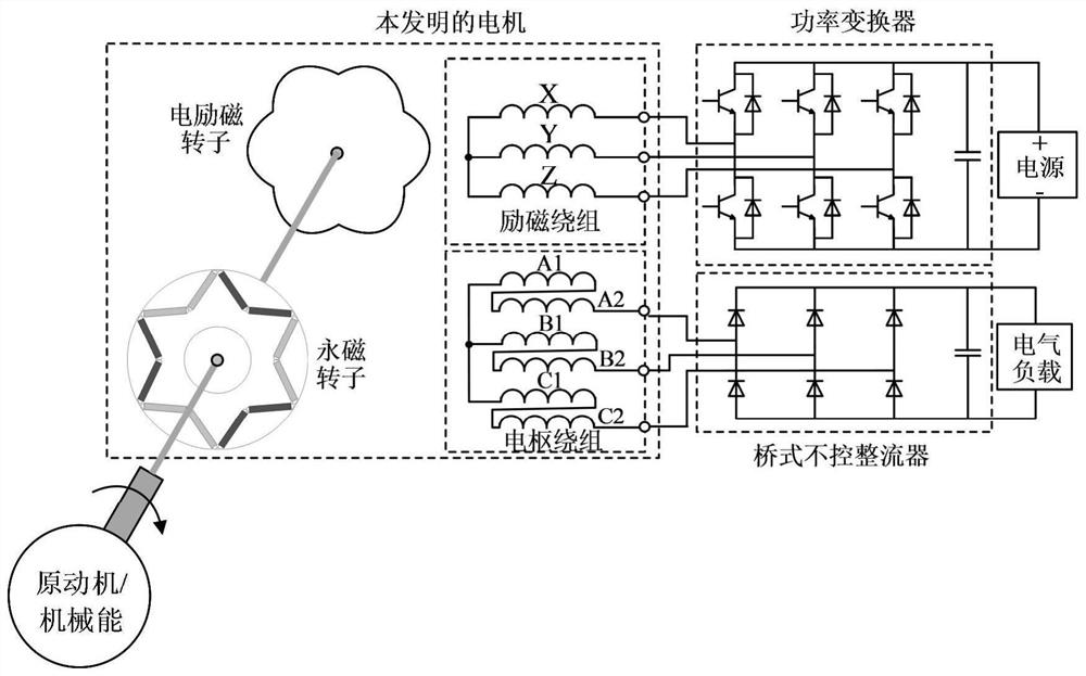
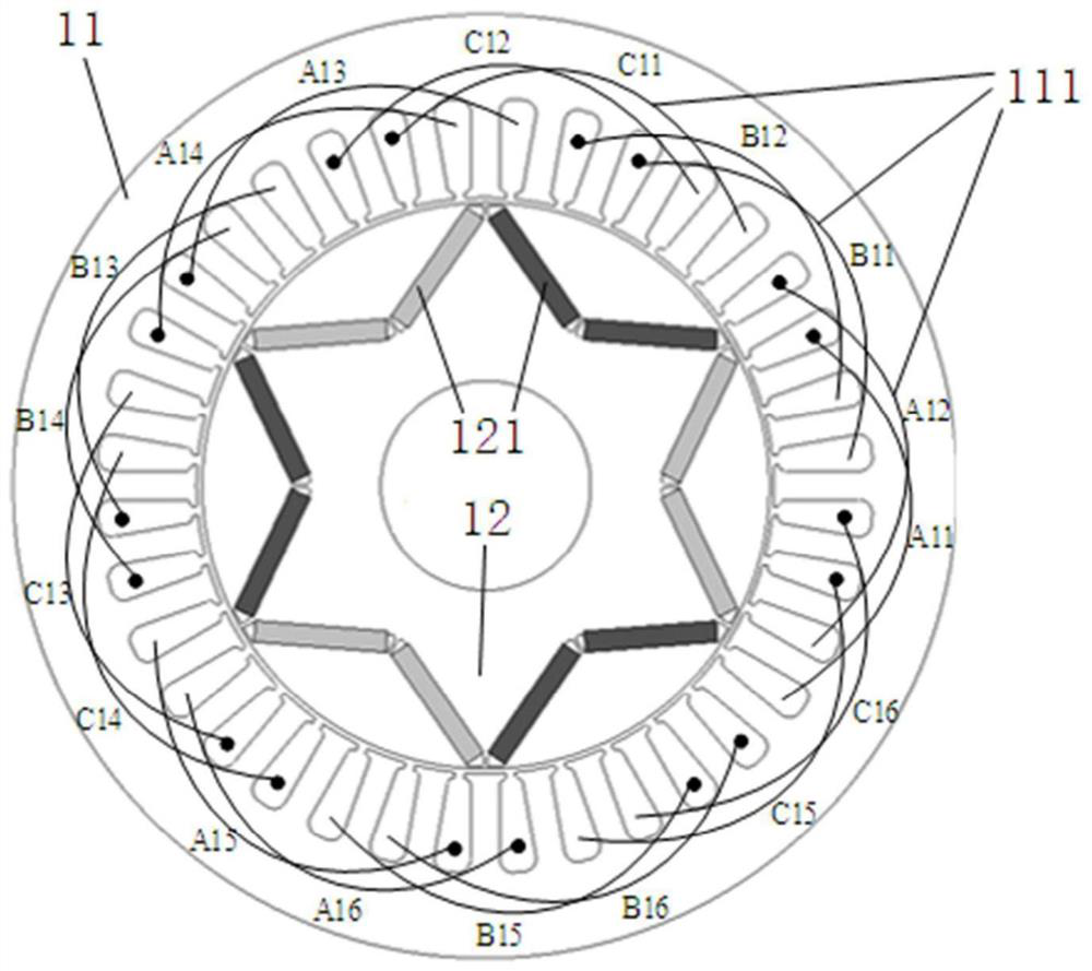
The invention discloses a parallel structure hybrid excitation brushless motor and its power generation system, comprising a parallel structure hybrid excitation brushless motor, a power converter, a power supply, an uncontrollable rectifier, a DC electrical load and an AC electrical load. The parallel structure hybrid excitation brushless motor includes a permanent magnet synchronous motor and an electric excitation synchronous reluctance motor arranged in parallel with a common rotating shaft; the permanent magnet synchronous motor includes an armature stator, a synchronous rotor and a permanent magnet; the armature stator is wound with an armature winding 1. The electric excitation synchronous reluctance motor includes an excitation stator and a reluctance rotor; the excitation stator is wound with two armature windings and an AC excitation winding, and the first and two phases of the armature winding are connected in series to form the total armature winding; the poles of the synchronous rotor are The number of pole pairs is equal to that of the reluctance rotor. By adjusting the magnitude and direction of the direct axis excitation current in the excitation winding, the voltage regulation of the total armature winding can be achieved. The invention has the advantages of high power density, adjustable magnetic field and no coupling between the excitation magnetic field and the permanent magnetic field.

Description

technical field [0001] The invention relates to the field of motor design and manufacture, in particular to a parallel structure hybrid excitation brushless motor and its power generation system. Background technique [0002] Permanent magnet motors have the advantages of high torque / power density, high efficiency and high power factor, and have been applied in many occasions. However, field weakening of PM motors is achieved by controlling the direct axis current component in the armature winding (- i d ) to achieve, the permanent magnet has the risk of irreversible demagnetization, and the weakening capacity is limited. Moreover, when permanent magnet motors are used in power generation occasions such as aviation power supplies, full-power controllable converters are required to achieve voltage regulation. [0003] Due to the existence of the rotor DC excitation winding, the air gap magnetic field of the electrically excited synchronous motor is easy to adjust. However...

Claims


Application Information

Patent Timeline
Patent Type & Authority Patents(China)
IPC IPC(8): H02K3/28H02K1/24H02K19/30H02K21/14
CPCH02K1/246H02K3/28H02K19/30H02K21/14
Inventor 李健王凯柳霖郑蓉蓉张涵刘闯
Owner NANJING UNIV OF AERONAUTICS & ASTRONAUTICS
Learn More