Novel photoelectric timer

A timer and photoelectric technology, applied in electronic timers, timers of integrated equipment, instruments, etc., can solve the problems of low efficiency, cumbersome operation, inconvenient use, etc., and achieve intuitive feedback and reminders, easy to implement, and reasonable design. Effect

Inactive Publication Date: 2020-02-21
罗利军
View PDF0 Cites 0 Cited by
  • Summary
  • Abstract
  • Description
  • Claims
  • Application Information

AI Technical Summary

Problems solved by technology

[0002] At present, most of the traditional timer products on the market require users to set and adjust the time through physical buttons. This method is not only inefficient, but also cumbersome and inconvenient to use.
Secondly, traditional timer products only have digital time display and no progress bar prompts, so they cannot give users clear and vivid progress feedback in time
At the same time, the only way for traditional timer products to remind users after the timing is over is through sound reminders, which makes users unable to use in some scenes that need to keep quiet

Method used


Image

  • Novel photoelectric timer
  • Novel photoelectric timer
  • Novel photoelectric timer

Examples


Embodiment Construction

[0023] The present invention will be described in detail below in conjunction with the accompanying drawings.

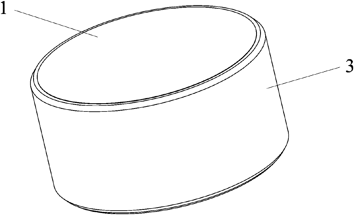
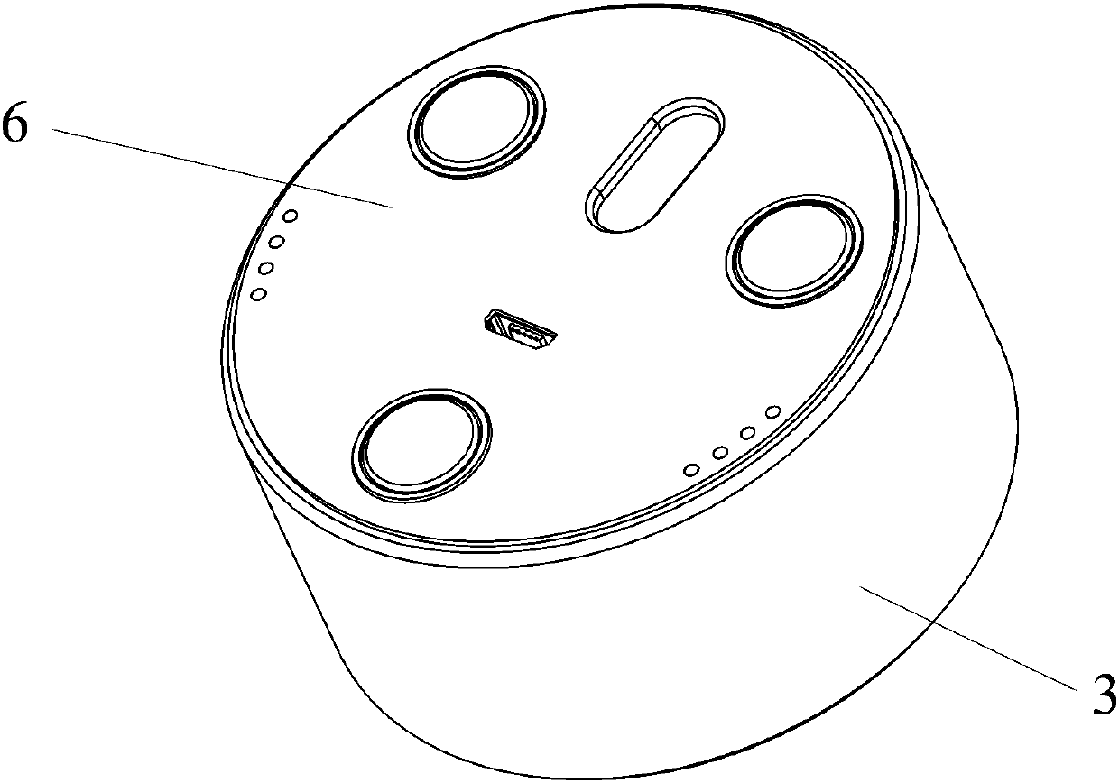
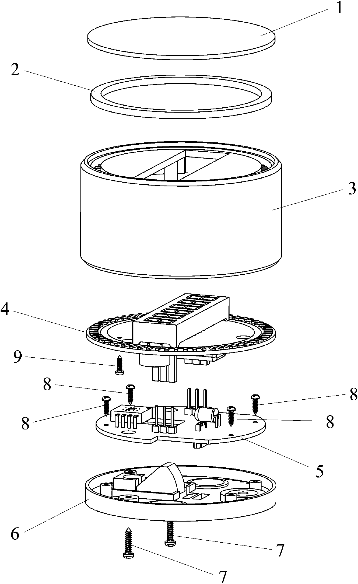
[0024] A new photoelectric timer mainly includes: screen 1, light guide ring 2, shell 3, PCB board 4, digital tube 4-5, LED light group 4-6, battery 4-8, control chip 4-9, bee Sounder 4-10, PCB board 2 5, infrared LED lamp 5-9, optical sensor 5-10, USB charging socket 5-11, light touch switch 5-12, bottom plate 6, switch button 6-15, optical lens 6-16, slip pad 6-19, magnet 6-13, screw one 7, screw two 8, screw three 9. It is characterized in that: the top of the housing 3 is provided with a logo one 3-2 and a logo two 3-3, wherein the logo one 3-2 represents the positive direction of the timer, and the logo two 3-3 represents the negative direction of the timer. The top of the housing 3 is provided with a light guide groove 3-1 and a rectangular hole 3-4. The size of the rectangular hole 3-4 is equivalent to that of the nixie tube 4-5, so that the nixie tube 4-5 ca...


PUM


Abstract

The invention relates to a novel photoelectric timer. The novel photoelectric timer mainly comprises a screen, a light guide ring, a shell, a PCB I, an LED lamp set, a nixie tube, a control chip, a battery, a buzzer, a PCB II, an infrared LED lamp, an optical lens, an optical sensor, a USB charging female base, a touch switch, a bottom plate, a magnet, a switch button and a sliding assisting pad.The novel photoelectric timer is characterized in that a light guide groove is formed in the top of the shell; the light guide ring is installed in the light guide groove; the screen is installed at the top of the shell; the nixie tube is located in the middle of the upper surface of the PCB I; the LED lamp set is arranged at equal intervals along the edge of the upper surface of the PCB I; the infrared LED lamp and the optical sensor are located on the upper surface of the PCB II; the optical sensor is located just above a rectangular hole II in the PCB II; and the optical lens is installed on the bottom plate, and a part of the optical lens penetrates through the rectangular hole II in the PCB II. The timer is ingenious and reasonable in structural design. A user can set time only by sliding the timer, and therefore, use efficiency is greatly improved.

Description

technical field [0001] The invention relates to a timer, in particular to a novel photoelectric timer. Background technique [0002] At present, most of the traditional timer products on the market require users to set and adjust the time through physical buttons. This method is not only inefficient, but also cumbersome and inconvenient to use. Secondly, traditional timer products only have digital time display and no progress bar prompts, so they cannot give users clear and vivid progress feedback in time. At the same time, the only way for traditional timer products to remind the user after the timing is over is through the sound reminder, which makes the user unable to use it in some scenes that need to keep quiet. Contents of the invention [0003] The object of the present invention is to provide a novel photoelectric timer to improve and solve the disadvantages and problems of the above-mentioned traditional timer. [0004] In order to achieve the above object, the...

Claims


Application Information

Patent Timeline
IPC IPC(8): G04G9/04G04G21/00
CPCG04G9/04G04G21/00
Inventor 罗利军
Owner 罗利军
Why Eureka
Try Eureka