
Quick clamping bracket of sighting telescope

A sight and fast technology, applied in the field of sight assembly, can solve the problems of inconvenient replacement, waste of time, unfavorable quick installation of sight, etc., to achieve the effect of increasing the speed of screwing and reducing the time

Inactive Publication Date: 2020-02-21
武汉皓梦源机械设备制造有限公司
View PDF0 Cites 3 Cited by
  • Summary
  • Abstract
  • Description
  • Claims
  • Application Information

AI Technical Summary

Problems solved by technology

[0004] 1. Since the installation and disassembly of the sight fixed by locking bolts usually requires the use of tools, it is not convenient to replace it at any time;
[0005] 2. During the assembly process of the upper mounting frame and the lower mounting frame of the scope base, it is generally necessary to align the mounting holes on the upper mounting frame and the lower mounting frame first, and then fix them with fastening bolts, so that the mounting holes are aligned Tends to waste a lot of time and is not conducive to the quick installation of the scope

Method used


Image

  • Quick clamping bracket of sighting telescope
  • Quick clamping bracket of sighting telescope
  • Quick clamping bracket of sighting telescope

Examples


Embodiment Construction

[0027] The following will clearly and completely describe the technical solutions in the embodiments of the present invention with reference to the accompanying drawings in the embodiments of the present invention. Obviously, the described embodiments are only some, not all, embodiments of the present invention.

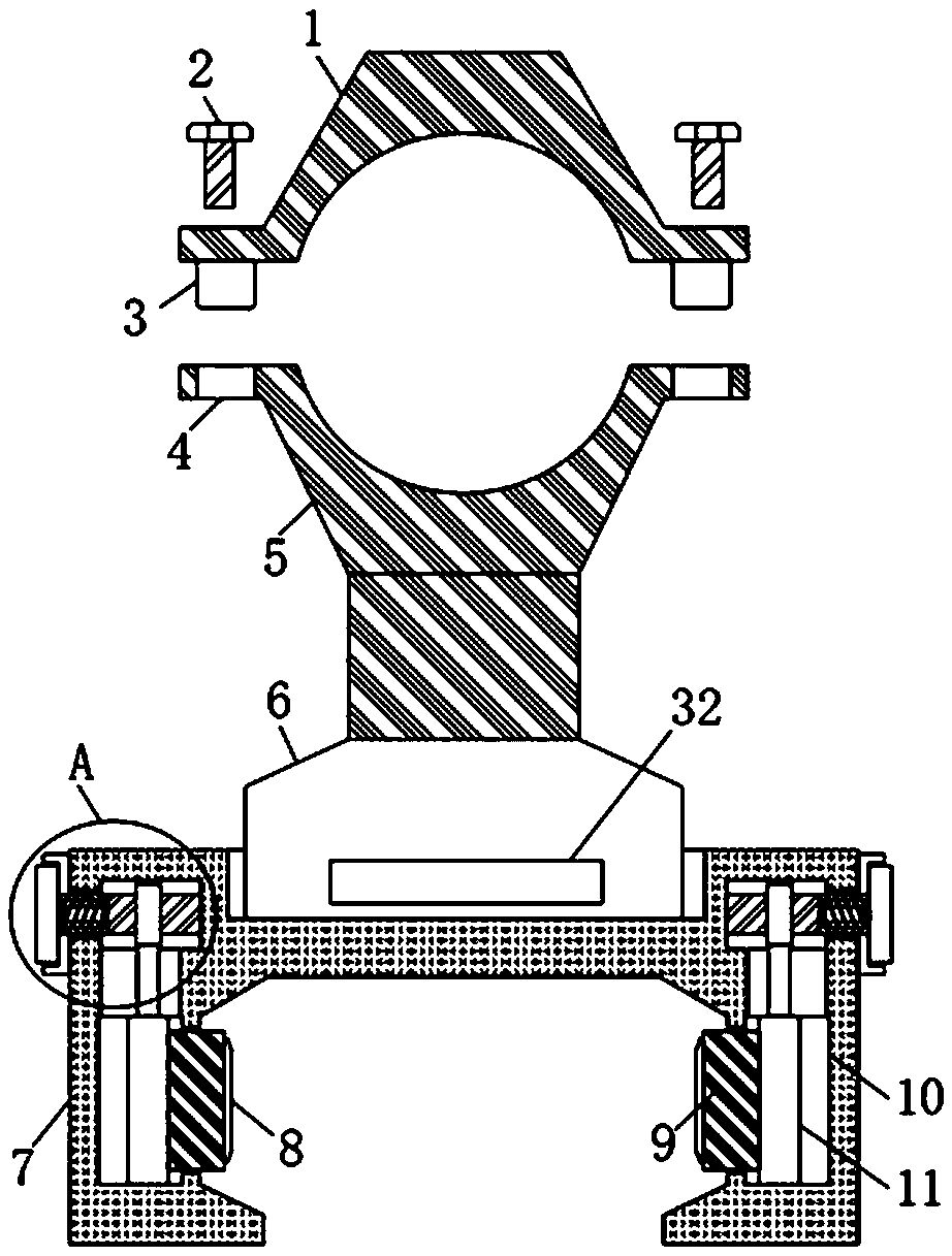
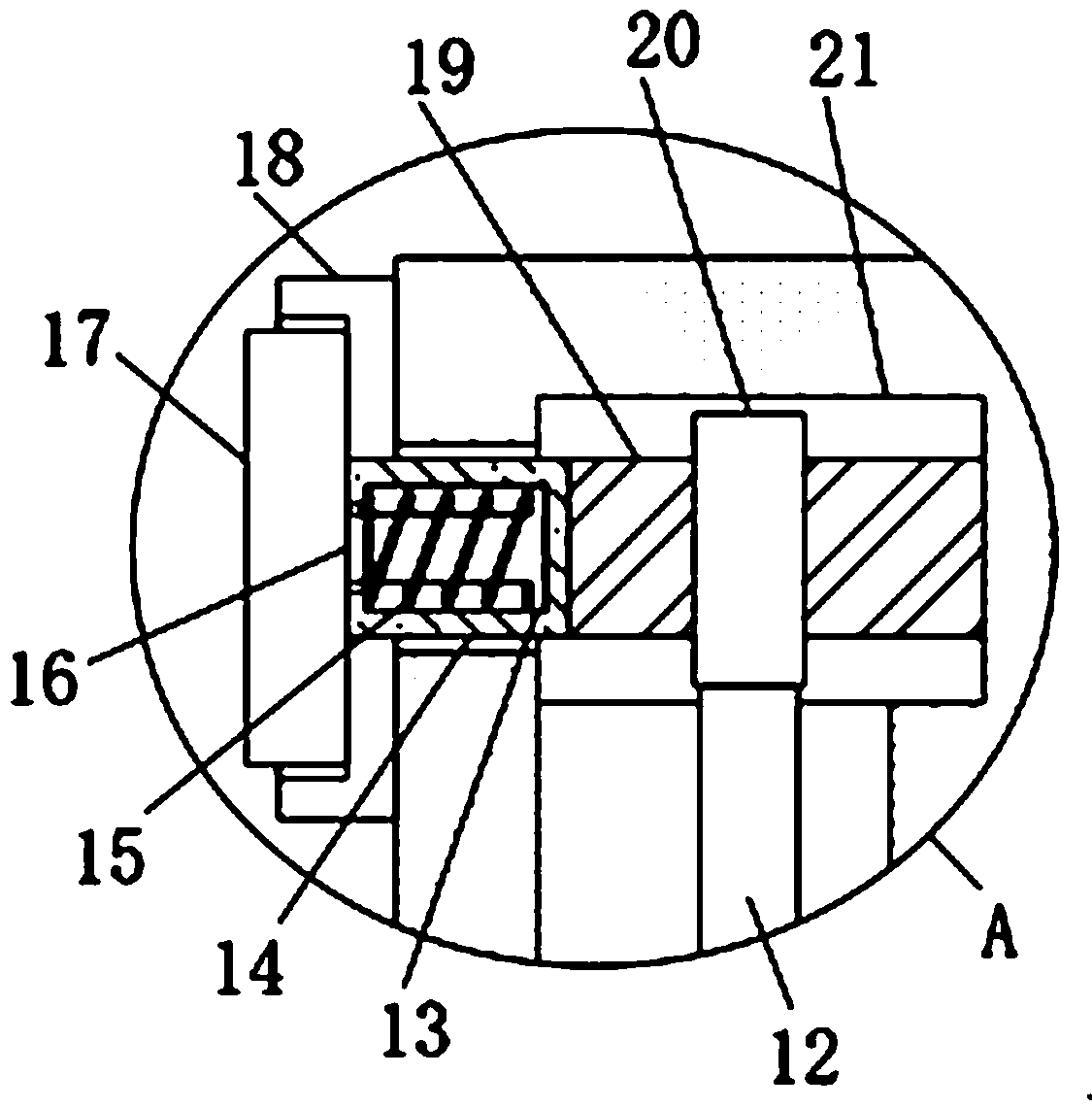
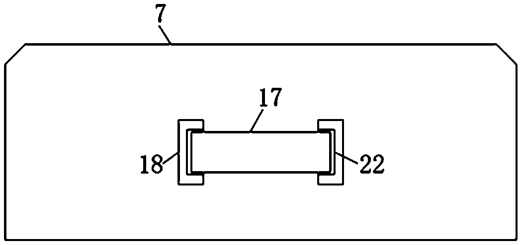
[0028] refer to Figure 1-5 , a fast clamping bracket for the scope, including a base 7 that can be connected to the guide rail that comes with the firearm. The inside of the base 7 is symmetrically provided with two circular cavities 21, and the inside of the circular cavity 21 is provided with a rotatable The threaded rod 19 is provided with a pressing mechanism for pressing against the guide rail, the outward end of the threaded rod 19 is fixedly connected with the rotating rod 14, and the end of the rotating rod 14 away from the threaded rod 19 extends to the outside of the circular cavity 21 , the rotating rod 14 is provided with a telescopic rotating mechanism,...


PUM


Abstract

The invention discloses a quick clamping bracket of a sighting telescope. The quick clamping bracket comprises a base capable of being connected with a guide rail on a gun, the interior of the base issymmetrically provided with two circular cavities, a rotatable threaded rod is arranged inside each circular cavity, each threaded rod is provided with a pressing mechanism for abutting against the guide rail, the outward end of each threaded rod is fixedly connected with a rotating rod, the end, far away from the corresponding threaded rod, of each rotating rod extends to the outside of the corresponding circular cavity, a retractable rotating mechanism is arranged on each rotating rod, and two limiting plates are symmetrically arranged on the outer side walls of the both ends of the base. The quick clamping bracket is reasonable in structure design, the positions of upper and lower mounting brackets can be quickly determined, alignment of mounting holes can be quickly realized, and theinstalling speed of the sighting telescope is effectively improved; the guide rail can be abutted through pressing plates, so that the installing stability of the base is ensured; and through the arrangement of anti-skid teeth, the abutting effect of the pressing plates can be improved, the better fixing effect is realized, and replacement can be carried out without using a tool.

Description

technical field [0001] The invention relates to the technical field of sight assembly, in particular to a fast clamping bracket for a sight. Background technique [0002] Sights, or optical sighting devices, have been telescopic sighting devices on guns before the 19th century, and sighting devices can be used for aiming in low-light conditions. Sights can be divided into holographic sights, inner red and green dot sights, and laser sights. They are generally installed on guns through the scope base. [0003] At present, the common sight bases on the market are often fixed on the gun guide rail by threaded locking bolts. This method of fixing the locking bolts has the following problems in actual use: [0004] 1. Since the installation and disassembly of the sight fixed by locking bolts usually requires the use of tools, it is not convenient to replace it at any time; [0005] 2. During the assembly process of the upper mounting frame and the lower mounting frame of the sc...

Claims


Application Information

Patent Timeline
Patent Type & Authority Applications(China)
IPC IPC(8): F41G11/00
CPCF41G11/001
Inventor 熊旭斌
Owner 武汉皓梦源机械设备制造有限公司
Learn More