
Adjustable cantilever

A cantilever device, adjustable technology, applied in the direction of machine/support, supporting machine, mechanical equipment, etc., can solve problems such as inconsistent load range, inconvenient use, and inability to judge

Active Publication Date: 2021-08-24
MODERNSOLID INDAL
View PDF0 Cites 0 Cited by
  • Summary
  • Abstract
  • Description
  • Claims
  • Application Information

AI Technical Summary

Problems solved by technology

[0004] However, since the driven seat is hidden in the end cover seat, the position of the driven seat cannot be known from the appearance of the cantilever device, and correspondingly, the telescopic seat cannot be known. The load range of the mechanism, so that when the adjustment bolt is turned, because the position of the follower seat cannot be judged, the actual load often does not conform to the load range of the telescopic mechanism, causing the suspended object It hangs down or rises up, but cannot be stabilized in a fixed position, causing inconvenience in use

Method used


Image

  • Adjustable cantilever
  • Adjustable cantilever
  • Adjustable cantilever

Examples


Embodiment Construction

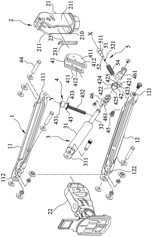
[0031] refer to figure 1 , figure 2 and image 3 , an embodiment of the adjustable cantilever device of the present invention includes a cantilever unit 1 , a joint unit 2 , a telescopic unit 3 , an adjustment unit 4 , and a pointing unit 5 .

[0032] refer to figure 1 , figure 2 , Figure 4 and Figure 5 , the cantilever unit 1 includes a first cantilever 11, a second cantilever 12 opposite to the first cantilever 11 and defining a channel 10 with the first cantilever 11. The first cantilever 11 has a first end 111 and a second end 112 opposite to each other. The second cantilever 12 has a first end 121 and a second end 122 opposite to each other.

[0033] The joint unit 2 includes a first joint seat 21 , a second joint seat 22 , and a panel 23 .

[0034] The first joint seat 21 is pivotally connected to the first end 111 of the first cantilever 11 and the first end 121 of the second cantilever 12, and has two plate walls 211 separated by a distance, and is connecte...


PUM


Abstract

An adjustable cantilever device includes a cantilever unit, a joint unit pivotally connected to the cantilever unit, a telescopic unit inserted in the cantilever unit, an adjustment unit for adjusting the telescopic unit, and a pointing unit. The joint unit includes a first joint base and a second joint base forming a four-bar linkage with the cantilever unit. The first joint base has an alcove with an opening facing one side, and a see-through portion formed on the other side for seeing through the alcove. The adjustment unit includes a link seat that is inserted in the alcove and connected with the movable part of the telescopic unit, and an adjustment bolt that is rotatably inserted in the first joint seat and threaded through the link seat. The link seat rotates with the adjustment bolt. The movement is relative to the displacement of the perspective part. The pointing unit is connected to the carrier. In this way, the present invention can display the position of the pointing unit through the see-through part, and then mark the load range that the telescopic unit can bear, and improve the convenience in use.

Description

technical field [0001] The invention relates to a cantilever device, in particular to an adjustable cantilever device. Background technique [0002] An existing cantilever device disclosed in Taiwan Patent No. M548619 is suitable for suspending an object (such as a screen). Referring to the patent No. M548619, the cantilever device mainly includes an upper arm and a lower arm that are upper and lower aligned with each other, and are pivotally connected with the upper arm and the lower arm to form one end of a four-bar linkage mechanism. The cover seat and a connecting seat, a telescopic mechanism inserted between the upper arm and the lower arm, a follower seat connected to a terminal section of the telescopic mechanism, and rotatably inserted in the end cover seat and screw through an adjusting bolt of the follower seat. [0003] When adjusting the load of the cantilever device, you only need to turn the adjusting bolt to drive the upward and downward displacement of the ...

Claims


Application Information

Patent Timeline
Patent Type & Authority Patents(China)
IPC IPC(8): F16M11/06F16M11/18
CPCF16M11/043F16M11/06F16M11/18F16M11/2092F16M11/24F16M2200/044F16M2200/063F16M11/046F16M11/048F16M11/08F16M11/2014F16M11/2021F16M13/02
Inventor 洪钦瑞
Owner MODERNSOLID INDAL
Learn More