
Thin film insulating core non-conducting electrode cap and annular nugget resistance spot welding method

A conductive electrode and electrode cap technology, applied in resistance welding equipment, electrode features, welding equipment, etc., can solve the problems of reducing the shear strength and corrosion resistance of the joint, overheating and large deformation of the joint, and achieve good cooling and heat dissipation performance. , Reduce the penetration rate and solve the effect of deep indentation

Inactive Publication Date: 2020-02-21
JILIN UNIV
View PDF7 Cites 5 Cited by
  • Summary
  • Abstract
  • Description
  • Claims
  • Application Information

AI Technical Summary

Problems solved by technology

[0005] The object of the present invention is to provide a non-conductive electrode cap with a film insulating core and a method for resistance spot welding of a ring-shaped nugget, which solves the problem of deep indentation and large deformation of the traditional resistance spot welding process, which easily reduces the shear strength and resistance of the joint. Corrosion ability etc.
In this way, the indentation and deformation of spot welding are reduced, and it is also beneficial to solve the problems of overheating and burn-through of the joint, and further improves the performance of the resistance spot welding joint

Method used


Image

  • Thin film insulating core non-conducting electrode cap and annular nugget resistance spot welding method
  • Thin film insulating core non-conducting electrode cap and annular nugget resistance spot welding method
  • Thin film insulating core non-conducting electrode cap and annular nugget resistance spot welding method

Examples


Embodiment Construction

[0035] The detailed content of the present invention and its specific implementation will be further described below in conjunction with the accompanying drawings.

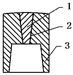
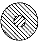
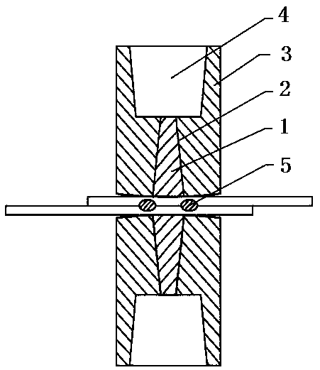
[0036] see Figure 1 to Figure 3 As shown, the film insulation core non-conductive electrode cap and the ring-shaped nugget resistance spot welding method of the present invention aim to reduce the indentation depth of the spot welding joint and the deformation of the workpiece, and further improve the joint performance of the resistance spot welding. The non-conductive electrode cap with film insulation core is mainly composed of two parts, namely the core part of the electrode cap and the peripheral part. Both parts are homogeneous materials with good thermal conductivity, and the heat dissipation effect is the same as that of traditional electrode caps. The outer surface of the core is sprayed with a layer of thin film insulating material to achieve the insulating effect. The core with a thin film insulating l...


PUM


Abstract

The invention relates to a thin film insulating core non-conducting electrode cap and an annular nugget resistance spot welding method, and belongs to the technical field of resistance spot welding. The thin film insulating core non-conducting electrode cap comprises an electrode cap core part and an electrode cap peripheral part, wherein the two parts are made of homogeneous materials with good thermal conductivity; a layer of thin film insulating material is sprayed on the outer side surface of the electrode cap core part; and the electrode cap core part with a thin film insulating layer isin interference fit with the electrode cap peripheral part. The electrode cap core part and the electrode cap peripheral part have the same spherical radius, and the two parts are in smooth transitionat the junction of the end faces. In the welding and electrifying process, due to the existence of the insulating layer, current can circulate in the peripheral area of the contact surface of the electrode cap and a workpiece, and annular current distribution is formed. Under the action of annular heat distribution, an annular nugget is formed between workpieces, and the reduction of the penetration rate under the condition of the same connecting area is realized, so that the joint strength is guaranteed under the condition that the welding heat input is reduced, the indentation and deformation are reduced, and the joint performance of resistance spot welding is further improved.

Description

technical field [0001] The invention relates to the technical field of resistance spot welding, in particular to a non-conductive electrode cap with a film insulation core and a resistance spot welding method for an annular nugget in the technical field of spot welding. Background technique [0002] The resistance spot welding process has the characteristics of low cost, high production efficiency, and easy mechanization and automation. It is widely used in automobile, rail passenger car, aerospace and other machinery manufacturing industries. According to statistics, the current resistance spot welding method has accounted for about a quarter of the entire welding workload, and there is a tendency to continue to increase. A large number of structural connections are made by resistance spot welding. For example, in the manufacturing process of stainless steel rail cars, the resistance spot welding process is widely used for car body structure connection, accounting for abou...

Claims


Application Information

Patent Timeline
Patent Type & Authority Applications(China)
IPC IPC(8): B23K11/11B23K11/30B23K11/36
CPCB23K11/11B23K11/30B23K11/36
Inventor 徐国成陶维承董娟谢俊林谷晓鹏
Owner JILIN UNIV
Learn More