Light emitting device and method for manufacturing same
A technology for light-emitting devices and light-emitting elements, which is applied to signal devices, lighting devices, semiconductor devices of light-emitting elements, etc., can solve the problems of reduced contrast of variable light distribution type headlamps, and achieve the effect of reducing image plane curvature.
- Summary
- Abstract
- Description
- Claims
- Application Information
AI Technical Summary
Problems solved by technology
Method used
Image
Examples
no. 1 approach
[0101] The first embodiment will be described.
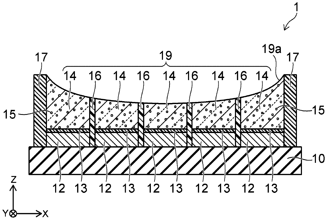
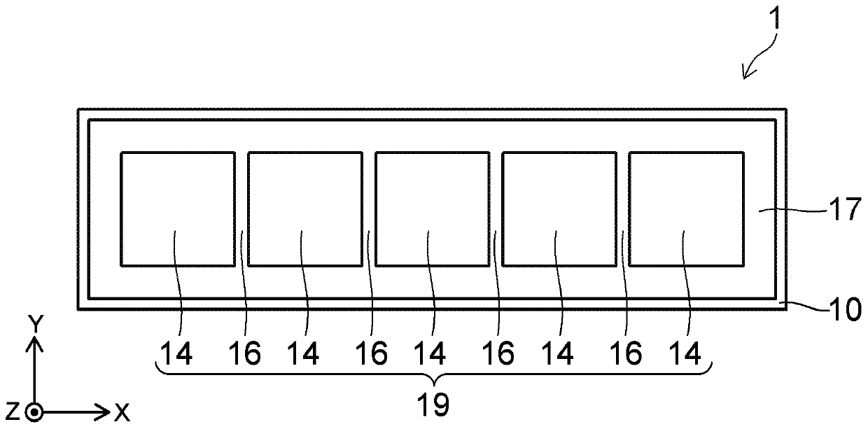
[0102] Figure 1A It is an end view showing the light emitting device of this embodiment. Figure 1B is its top view.
[0103] The configuration of the light emitting device 1 of this embodiment will be schematically described. The light emitting device 1 includes a substrate 10 , a plurality of light emitting elements 12 , a plurality of phosphor members 14 as wavelength conversion members, and a light reflection layer 16 . The light emitting element 12 is mounted on the substrate 10 . Each phosphor member 14 is provided on each light emitting element 12 and includes phosphor particles 15 . The light reflection layer 16 is arranged between adjacent phosphor members 14 . Moreover, the upper surface 19a of the aggregate 19 which consists of several fluorescent substance members 14 and the light reflection layer 16 is a concave curved surface.
[0104] The details will be described below. A substrate 10 is provided in the li...
no. 2 approach
[0137] Next, a second embodiment will be described.
[0138] Figure 7 It is an end view showing the light emitting device of this embodiment.
[0139] The difference between the light emitting device 2 of the present embodiment and the light emitting device 1 of the first embodiment described above is that a wavelength conversion member 24 is provided instead of the phosphor member 14 . The wavelength converting members 24 are provided in the same number as the light emitting elements 12 . Each wavelength conversion member 24 is provided with a phosphor member 21 , an adhesive layer 22 , and a glass member 23 .
[0140] Specifically, phosphor member 21 is bonded to the upper surface of each light emitting element 12 via adhesive layer 13 . The respective phosphor members 21 have substantially the same thickness. Phosphor particles 15 are dispersed in phosphor member 21 . The concentration of phosphor particles 15 is substantially equal between phosphor members 21 . The ...
no. 3 approach
[0156] Next, a third embodiment will be described.
[0157] Figure 9 It is an end view showing the light emitting device of this embodiment.
[0158] The difference between the light emitting device 3 of this embodiment and the light emitting device 1 of the first embodiment described above is that an adhesive layer 31 is provided instead of the adhesive layer 13 .
[0159] Phosphor particles 15 are contained in adhesive layer 31 . The concentration of the phosphor particles 15 in the adhesive layer 31 is high in the central portion of the light emitting device 3 in the X direction, and becomes lower toward both ends in the X direction. That is, compared to the concentration of phosphor particles 15 in the adhesive layer 31 arranged on the light emitting element 12 mounted on the central portion of the substrate 10 in the X direction, the concentration of the phosphor particles 15 in the light emitting elements mounted on both ends of the substrate 10 in the X direction Th...
PUM
| Property | Measurement | Unit |
|---|---|---|
| length | aaaaa | aaaaa |
| depth | aaaaa | aaaaa |
Abstract
Description
Claims
Application Information
 - Generate Ideas
- Intellectual Property
- Life Sciences
- Materials
- Tech Scout
- Unparalleled Data Quality
- Higher Quality Content
- 60% Fewer Hallucinations
Browse by: Latest US Patents, China's latest patents, Technical Efficacy Thesaurus, Application Domain, Technology Topic, Popular Technical Reports.
© 2025 PatSnap. All rights reserved.Legal|Privacy policy|Modern Slavery Act Transparency Statement|Sitemap|About US| Contact US: help@patsnap.com


