
Stirring device for powder material mixing

A stirring device and mixing technology, applied in mixers, transportation and packaging, shaking/oscillating/vibrating mixers, etc., can solve the problems of reducing the impact force of dust, affecting the mixing effect of powder materials, etc., to increase the probability of impact, Simple structure, improve the effect of mixing effect

Inactive Publication Date: 2020-02-18
安徽东阳矿业科技有限公司
View PDF0 Cites 0 Cited by
  • Summary
  • Abstract
  • Description
  • Claims
  • Application Information

AI Technical Summary

Problems solved by technology

[0004] What the present invention is to overcome is that when the stirring shaft in the existing stirring device rotates in the stirring barrel, the dust driven in the stirring barrel can only move in the same direction, so that the impact force between the dusts is reduced, which affects the mixing effect of the powder. The purpose is to provide a stirring device for powder mixing

Method used


Image

  • Stirring device for powder material mixing
  • Stirring device for powder material mixing
  • Stirring device for powder material mixing

Examples


Embodiment 1

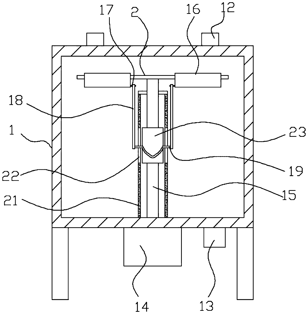
[0024] Such as figure 1 Shown; A stirring device for powder mixing, comprising:

[0025] Stirring barrel 1, the upper part of the stirring barrel 1 is provided with a material inlet 12, the lower part is provided with a discharge port 13, the bottom of the stirring barrel 1 is equipped with a driving motor 14, and the inside is provided with a stirring shaft 15, and the driving motor 14 is a stirring shaft 15 provide power;

[0026] The support rod 2 is vertically fixed on the upper part of the stirring shaft 15, and the connection between the stirring shaft 15 and the support rod 2 divides the support rod 2 into two sections, each section of the support rod is hinged with a flap 16, and the lower end of the flap 16 is close to the One side of the stirring shaft 15 is provided with a boss 17, the boss 17 is hinged with a push rod 18, and a slider 19 is installed at the lower end of the push rod 18;

[0027] A sleeve 21 is installed inside the mixing barrel body 1, and the sl...

Embodiment 2

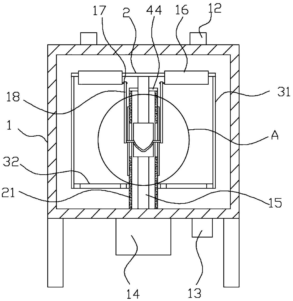
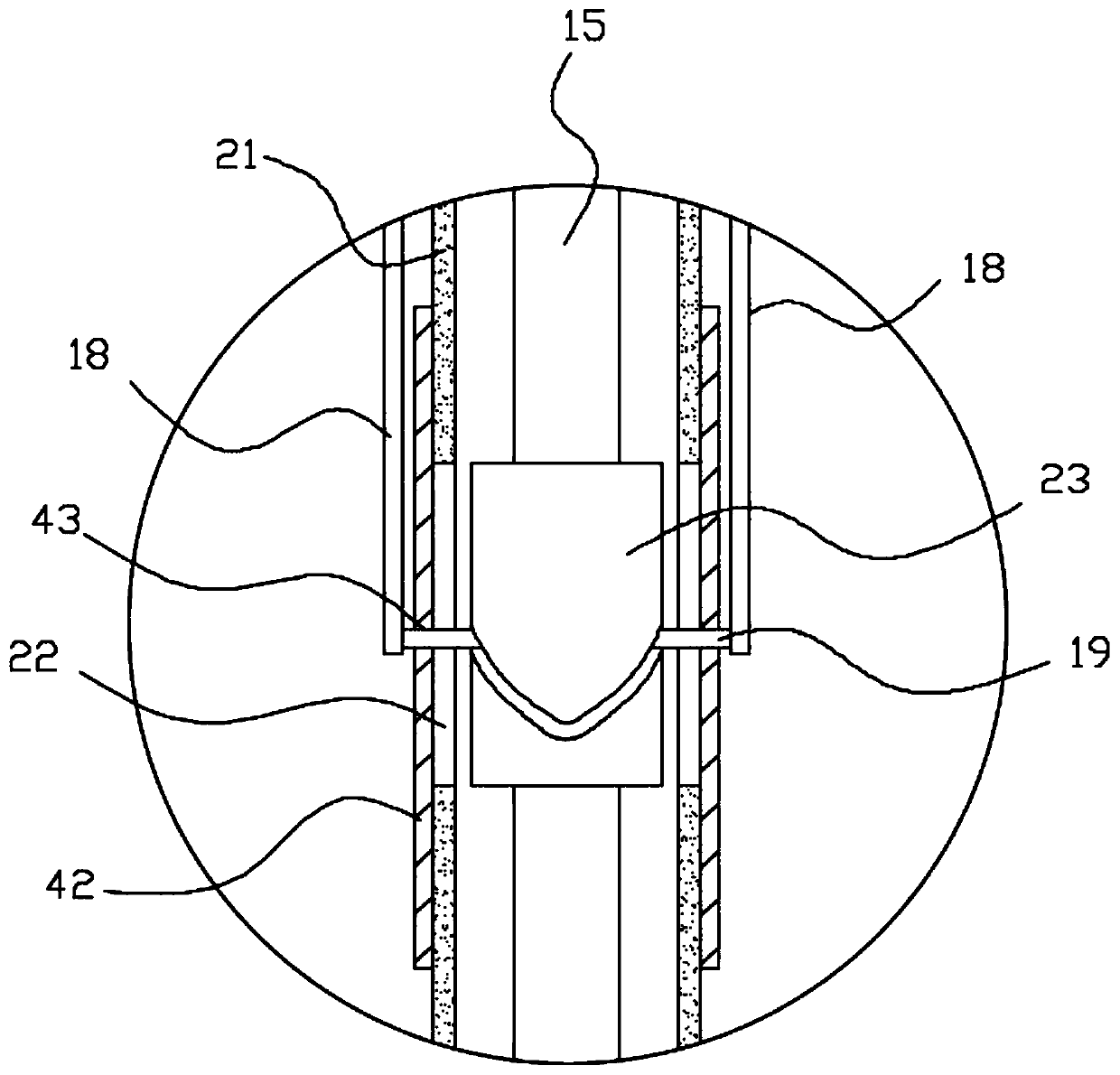
[0031] Such as figure 2 , image 3 , Figure 4 Shown; A stirring device for powder mixing, comprising:

[0032] Stirring barrel 1, the upper part of the stirring barrel 1 is provided with a material inlet 12, the lower part is provided with a discharge port 13, the bottom of the stirring barrel 1 is equipped with a driving motor 14, and the inside is provided with a stirring shaft 15, and the driving motor 14 is a stirring shaft 15 provide power;

[0033] The support rod 2 is vertically fixed on the upper part of the stirring shaft 15, and the connection between the stirring shaft 15 and the support rod 2 divides the support rod 2 into two sections, each section of the support rod is hinged with a flap 16, and the lower end of the flap 16 is close to the One side of the stirring shaft 15 is provided with a boss 17, the boss 17 is hinged with a push rod 18, and a slider 19 is installed at the lower end of the push rod 18;

[0034] A sleeve 21 is installed inside the mixing...


PUM


Abstract

The invention discloses a stirring device for powder material mixing and relates to the field of powder material processing equipment. The stirring device comprises a stirring bucket and a support rod, wherein a feeding hole is formed in the upper part of the stirring bucket; a discharge hole is formed in the lower part of the stirring bucket; a driving motor is mounted at the bottom of the stirring shaft; the stirring bucket is internally provided with a stirring shaft; the driving motor is used for providing power to the stirring shaft; the support rod is divided into two sections at the connecting part of the stirring shaft and the support rod; a flip plate is hinged with each section of the support rod; convex columns are arranged at lower ends of the flip plates and on sides close tothe stirring shaft; jack rods are hinged with the convex columns; sliding blocks are mounted at lower ends of the jack rods; the stirring bucket is internally provided with a sleeve; the sleeve is arranged outside the stirring shaft in a sleeving manner; the upper end of the stirring shaft extends outside the sleeve; chutes are formed in side surfaces of the sleeve along an axis direction; a column groove cam is fixedly mounted on the stirring shaft; and the sliding blocks penetrate through the chutes and are inserted into curved slots of the column groove cams. The collision rate of powder materials is increased, and the mixing effect of the powder material is improved.

Description

technical field [0001] The invention relates to the field of powder processing equipment, in particular to a stirring device for powder mixing. Background technique [0002] In the powder processing and production process, it is necessary to mix different powder materials. By spraying the powder materials into the mixing device, the impact between the powder materials is used to reduce the particle size of the powder materials and improve the mixing effect between the powder materials. [0003] In the daily production process, when the stirring shaft in the mixing equipment rotates, a wind pressure is formed inside the mixing barrel, which makes the powder move in one direction in the mixing barrel. Since the moving direction of the powder is the same, the impact force between the powder is reduced, which is easy to cause The powder is not mixed evenly. Contents of the invention [0004] What the present invention aims to overcome is that in the existing stirring device, ...

Claims


Application Information

Patent Timeline
IPC IPC(8): B01F11/00
CPCB01F31/441
Inventor 秦安山刘冠东郭雨
Owner 安徽东阳矿业科技有限公司
Learn More