Air flow modification device for air conditioners, indoor unit comprising same air flow modification device, and air conditioner comprising same indoor unit

A technology for changing wind direction, air conditioners, applied to heating and ventilation hoods/covers, air flow control elements, etc., can solve problems such as reduced air conditioning performance, condensation, etc., and achieve the effect of suppressing the reduction of wind volume

Active Publication Date: 2020-02-14
MITSUBISHI ELECTRIC CORP
View PDF22 Cites 0 Cited by
  • Summary
  • Abstract
  • Description
  • Claims
  • Application Information

AI Technical Summary

Problems solved by technology

For air conditioners, if the air volume of the exhaust air passing between the left and right wind direction deflection blades and the casing is reduced, the air conditioning performance may be reduced or condensation may occur.

Method used


Image

  • Air flow modification device for air conditioners, indoor unit comprising same air flow modification device, and air conditioner comprising same indoor unit
  • Air flow modification device for air conditioners, indoor unit comprising same air flow modification device, and air conditioner comprising same indoor unit
  • Air flow modification device for air conditioners, indoor unit comprising same air flow modification device, and air conditioner comprising same indoor unit

Examples


Embodiment approach 1

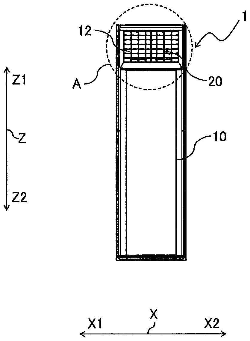
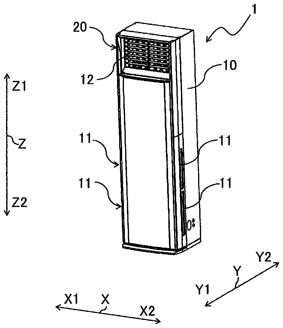
[0036] figure 1 It is a front view showing a schematic configuration of the indoor unit 1 of the air conditioner provided with the wind direction changing device 20 according to Embodiment 1 of the present invention. figure 2 It is a perspective view which shows the schematic structure of the indoor unit 1 of the air conditioner provided with the wind direction changing apparatus 20 which concerns on Embodiment 1 of this invention. For the wind direction changing device 20, cite figure 1 and figure 2 The illustrated floor-standing indoor unit 1 will be described as an example. Additionally, when including figure 1 In the drawings included below, the relative dimensional relationship and shape of each component may be different from the actual ones. In addition, for easy understanding, terminology indicating directions (such as "upper", "lower", "right", "left", "front", "rear", etc.) The term does not limit the invention of the present application. figure 1 The shown X...

Embodiment approach 2

[0111] Figure 27 It is a schematic diagram which shows the structural example of the air conditioner 100 which concerns on Embodiment 2 of this invention. The air conditioner 100 is an air conditioner using the indoor unit 1 including the wind direction changing device 20 according to the first embodiment. pair with Figure 1 to Figure 26 Portions with the same configuration as the wind direction changing device 20 are denoted by the same reference numerals, and description thereof will be omitted. Next, an air conditioner 100 including the wind direction changing device 20 of the above-mentioned embodiment will be described as Embodiment 2 of the present invention. exist Figure 27 The arrows in the middle solid line indicate the flow of the refrigerant during the cooling operation of the air conditioner 100 , and the arrows with broken lines indicate the flow of the refrigerant during the heating operation of the air conditioner 100 . Figure 27 The air conditioner 100 ...


PUM


Abstract

An air flow modification device for air conditioners comprises a rectangular frame that forms an opening, a plurality of horizontal air flow plates that are disposed in the frame opening in a line, and a connection plate that connects the plurality of horizontal air flow plates. The horizontal air flow plates comprise end air flow plates and one or more center air flow plates that are disposed between the end air flow plates. The end air flow plate comprises an end front air flow plate and an end back air flow plate that revolves in the direction opposite to the direction in which the end front air flow plate revolves and that is connected to the end front air flow plate so as to freely revolve. The center air flow plate comprises a center front air flow plate and a center back air flow plate that revolves in the direction opposite to the direction in which the center front air flow plate revolves and that is connected to the center front air flow plate so as to freely revolve. The connection plate engages and revolves the end front air flow plates, the end back air flow plates, the center front air flow plate, and the center back air flow plate. The angle through which the end front air flow plate revolves is smaller than the angle through which the center front air flow plate revolves, and the angle through which the end back air flow plate revolves is smaller than the anglethrough which the center back air flow plate revolves.

Description

technical field [0001] The present invention relates to an airflow direction changing device for an air conditioner that changes the airflow direction of exhaust air, an indoor unit provided with the airflow direction changing device, and an air conditioner provided with the indoor unit. Background technique [0002] Patent Document 1 discloses a wind direction deflecting device for an air conditioner in which a plurality of left and right wind direction deflecting blades are rotatably mounted in a discharge grill. Buckling away from the center of the discharge grid. [0003] Patent Document 1: Japanese Patent Application Laid-Open No. 62-56734 [0004] However, in the air conditioner described in Patent Document 1, if the angle of the left and right wind direction deflector vanes is increased, the left and right wind direction deflector vanes block the air passage between the left and right wind direction deflector vanes and the casing. As a result, the air conditioner ma...

Claims


Application Information

Patent Timeline
Patent Type & Authority Applications(China)
IPC IPC(8): F24F13/20F24F13/15
CPCF24F13/15F24F13/20
Inventor 平野雄大古田辰夫
Owner MITSUBISHI ELECTRIC CORP
Why Eureka
Try Eureka