
Power distribution cabinet

A technology for power distribution cabinets and top covers, which is applied to the substation/power distribution device shell, electrical components, substation/switch layout details, etc. It can solve the problems that cannot meet the needs of power distribution cabinets, etc., so as to facilitate fixed installation and strengthen the baffle The effect of intensity

Active Publication Date: 2020-02-14
NANJING SWITCHGEAR FACTORY
View PDF7 Cites 0 Cited by
  • Summary
  • Abstract
  • Description
  • Claims
  • Application Information

AI Technical Summary

Problems solved by technology

[0003] Due to structural design reasons, existing conventional power distribution boxes all have shells that are connected by bolts, or use an integral package. Patent CN106532466B discloses a power distribution cabinet shell that can be waterproof and monitor humidity, and the cabinet body can be raised and lowered, but Metal bolts and connecting shafts are indispensable for the installation of the overall cabinet shell structure, which cannot meet the market's demand for the safety of the power distribution cabinet, so a power distribution cabinet is urgently needed to solve this problem

Method used


Image

  • Power distribution cabinet
  • Power distribution cabinet
  • Power distribution cabinet

Examples


Embodiment Construction

[0032] The standard parts used in the present invention can be purchased from the market, and the special-shaped parts can be customized according to the instructions and the records of the drawings. The specific connection methods of each part are fixed by mature torsion springs in the prior art. Conventional means such as gold soldering, tape sticking, etc., will not be described in detail here.

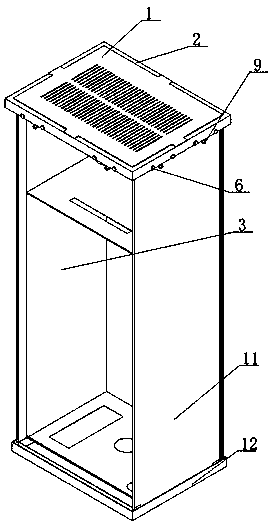
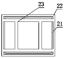
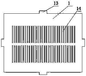
[0033] refer to Figure 1-16, a specific embodiment of the present invention comprises top cover 1, and top cover 1 is provided with several mutually parallel ventilation strips 14, and the edge of top cover 1 is fixed with side piece 13, and filter screen 15 is fixed in ventilation strip 14, and top frame 2 is connected to the top cover 1 through the side block 13, the bottom of the top frame 2 is welded with a strip plate 23, the strip plate 23 is connected to the body 3 of the power distribution cabinet, the bottom of the body 3 of the power distribution cabinet is connected to ...


PUM


Abstract

The invention discloses a power distribution cabinet. The power distribution cabinet comprises a top cover, wherein an edge block is fixed on an edge of the top cover, a top frame is connected with the top cover through the edge block, a strip-shaped plate is welded at the bottom of the top frame, the strip-shaped plate is connected with a power distribution cabinet body, the bottom of the power distribution cabinet body is connected with a base plate, four mounting grooves which are connected end to end are formed on an edge of the bottom plate, a baffle plate is clamped in each mounting groove, the baffle plate is clamped with a top frame, the top frame comprises an upper plate, a lower plate is welded on an outer side of the upper plate, a spring fixing piece is fixed at the bottom of the lower plate, a positioning hole is formed in the spring fixing piece, one end of a left spring is inserted into the positioning hole, the other end of the left spring is sleeved with a spring pressing plate, the spring pressing plate comprises a supporting plate, a left positioning hole and a right positioning hole are formed on the supporting plate, the left positioning hole is sleeved with the left spring, the right positioning hole is sleeved with a right spring, and a positioning pull plate is fixed to the top of the supporting plate. The power distribution cabinet is advantaged in thatdefects in the prior art can be overcome, and bolt-free connection of a cabinet body shell of the power distribution cabinet is achieved.

Description

technical field [0001] The invention relates to the field of installation of a power distribution cabinet, in particular to a power distribution cabinet in which the shell of the cabinet is connected without bolts. Background technique [0002] The function of the power distribution cabinet is to control and distribute power to various load parts, and to perform power-off maintenance when the circuit is short-circuited, overloaded and leaked. The types of distribution cabinets include fixed panel distribution cabinets, protective distribution cabinets, drawer type distribution cabinets and power lighting distribution cabinets. [0003] Due to structural design reasons, existing conventional power distribution boxes all have shells that are connected by bolts, or use an integral package. Patent CN106532466B discloses a power distribution cabinet shell that can be waterproof and monitor humidity, and the cabinet body can be lifted, but Metal bolts and connecting shafts are in...

Claims


Application Information

Patent Timeline
Patent Type & Authority Applications(China)
IPC IPC(8): H02B1/30
CPCH02B1/30H02B1/301
Inventor 不公告发明人
Owner NANJING SWITCHGEAR FACTORY
Learn More