
Lock with hinge function

A hinged and functional technology, used in building locks, door/window accessories, folding panels, etc., can solve problems such as affecting appearance, falling, and troublesome operation.

Pending Publication Date: 2020-02-14
NINGBO WANGTONG LOCKS
View PDF0 Cites 0 Cited by
  • Summary
  • Abstract
  • Description
  • Claims
  • Application Information

AI Technical Summary

Problems solved by technology

[0002] A hinge, also known as a hinge, is a mechanical device used to connect two solids and allow relative rotation between the two. The hinge can be composed of movable components or foldable materials. The hinge is mainly installed on doors and windows. Hinges are more installed on electrical cabinets, cabinets, cabinets and cabinets. According to the classification of materials, they are mainly divided into stainless steel hinges and iron hinges. In order to let people enjoy better, hydraulic hinges have appeared. It brings a buffer function when the cabinet door is closed, which minimizes the noise caused by the collision with the cabinet body; the current hinges are mainly used on doors, windows and cabinets, and are rarely used on locks, and most of the locks that people use now are Open with a key or password; for example, locks are usually installed in the cabinets at home. The locks are installed in these places to keep the cabinet doors stable. When there are too many items in the cabinets, the items will squeeze the cabinet doors open, affecting the overall appearance. In severe cases, items may even fall from the cabinet. It is troublesome to open the door with a key or code, and the door cannot be simply closed.

Method used


Image

  • Lock with hinge function
  • Lock with hinge function
  • Lock with hinge function

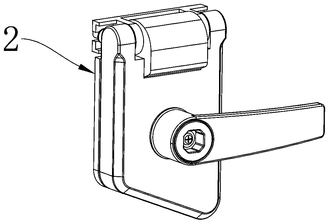
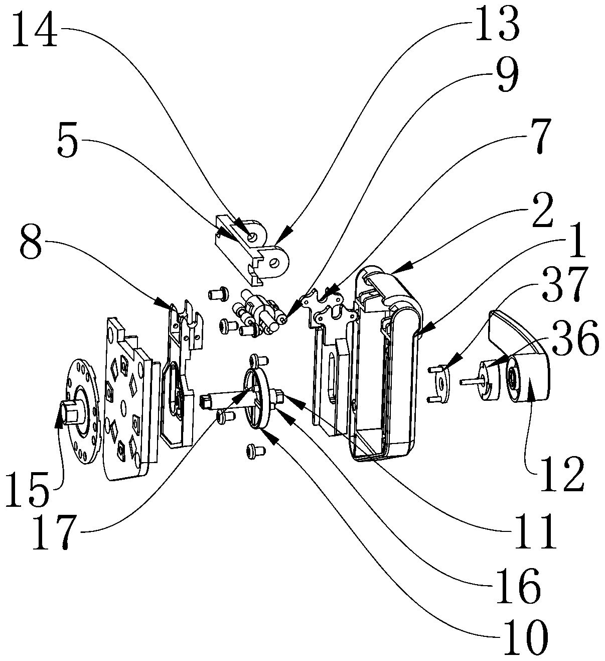
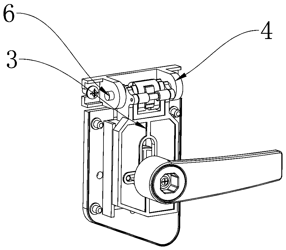
Examples


Embodiment Construction

[0023] The technical solutions of the various embodiments of the present invention will be clearly and completely described below in conjunction with the accompanying drawings. Apparently, the described embodiments are only some of the embodiments of the present invention, not all of them. Based on the embodiments described in the present invention, all other embodiments obtained by persons of ordinary skill in the art without creative efforts are within the protection scope of the present invention.

[0024] Such as Figure 1 to Figure 6 As shown, the present invention discloses a lock with a hinge function, which is characterized in that it includes a hinge base 1, an installation base 2 and a lock body 3, and the lock body 3 and the hinge base 1 pass through a middle The shaft structure 4 is connected, the central shaft structure 4 includes a hinge base 5 and a connecting rod 6, the hinge base 1 is arranged on the installation base 2, and the lock body 3 is arranged on the ...


PUM


Abstract

The invention discloses a lock with a hinge function. The lock comprises a hinge seat, an installation base and a lock body. The lock body is connected with the hinge seat through a middle shaft structure. The middle shaft structure comprises a hinge base and a connecting rod. The hinge seat is arranged on the installation base. The lock body is arranged in the hinge seat. The lock body comprisesa first lock body and a second lock body, wherein the first lock body and the second lock body are movably connected to the connecting rod. Limiting rods are symmetrically arranged on the two sides ofthe connecting rod, a disc is arranged between the first lock body and the second lock body, and the disc is connected with a pin shaft. The pin shaft is connected with a handle, a protruding pillaris arranged on the disc, and the protruding cylinder drives the first lock body and the second lock body to rotate. By means of the lock with the hinge function, after locking, the lock can be used asthe hinge, after unlocking, a whole door can be taken off, and use is convenient.

Description

technical field [0001] The invention relates to a lock, in particular to a lock with a hinge function. Background technique [0002] A hinge, also known as a hinge, is a mechanical device used to connect two solids and allow relative rotation between the two. The hinge can be composed of movable components or foldable materials. The hinge is mainly installed on doors and windows. Hinges are more installed on electrical cabinets, cabinets, cabinets and cabinets. According to the classification of materials, they are mainly divided into stainless steel hinges and iron hinges. In order to let people enjoy better, hydraulic hinges have appeared. It brings a buffer function when the cabinet door is closed, which minimizes the noise caused by the collision with the cabinet body; the current hinges are mainly used on doors, windows and cabinets, and are rarely used on locks, and most of the locks that people use now are Open with a key or password; for example, locks are usually i...

Claims


Application Information

Patent Timeline
IPC IPC(8): E05B63/14E05B3/00E05B15/00E05B17/00E05D7/04E05D5/02
CPCE05B3/00E05B15/00E05B17/00E05B63/143E05D5/0276E05D7/04E05D2007/0469
Inventor 韩文杰王壤
Owner NINGBO WANGTONG LOCKS
Learn More