
Heat flow control system and method for thermal environment simulation test of attitude control power system

A thermal environment simulation and power system technology, applied in space navigation conditions simulation devices, space navigation equipment, transportation and packaging, etc., can solve the lack of continuity and reliability of heat flux control of lamp arrays, lack of early warning and emergency treatment, etc. question

Active Publication Date: 2020-02-14
XIAN AEROSPACE PROPULSION TESTING TECHN INST
View PDF9 Cites 6 Cited by
  • Summary
  • Abstract
  • Description
  • Claims
  • Application Information

AI Technical Summary

Problems solved by technology

[0006] The main purpose of the present invention is to solve the technical problems of lack of continuity and reliability in heat flux control of lamp arrays in the prior art, and there is no early warning and emergency treatment if the heat flux measurement deviates greatly during the process, and to provide an attitude control power system Thermal environment simulation test heat flow control system and method

Method used


Image

  • Heat flow control system and method for thermal environment simulation test of attitude control power system
  • Heat flow control system and method for thermal environment simulation test of attitude control power system
  • Heat flow control system and method for thermal environment simulation test of attitude control power system

Examples


Embodiment 1

[0055] Embodiment 1: Closed-loop control method

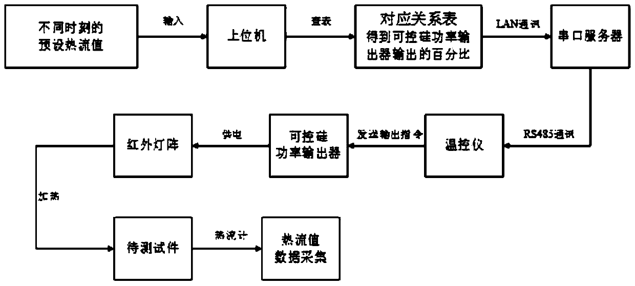
[0056] Such as figure 1 As shown, the specific method of closed-loop control is as follows:

[0057] 1) Set the proportional, integral and differential control parameters under different target heat flow values; establish the corresponding relationship of membership function and control rules corresponding to different target heat flow values; make the corresponding relationship table between heat flow value and control parameters;

[0058] 2) According to the required heat flux curve, by means of interpolation, the corresponding heat flow value is obtained at intervals of one second, and the corresponding relationship table between time and heat flow value is made.

[0059] During the test, the heat flow value of the heat flow meter is collected by the temperature controller; the upper computer reads the heat flow value collected by the temperature controller in LAN mode, and obtains the corresponding target heat flow value a...

Embodiment 2

[0068] Embodiment 2, open-loop control method

[0069] Such as figure 2 As shown, the specific method of open-loop control is as follows:

[0070] 1) According to the required heat flux curve, by means of interpolation, the corresponding heat flow value is obtained at intervals of 5 seconds, and the corresponding relationship table between time and heat flow value is made. Wherein the time interval of the closed-loop control interpolation in embodiment 1 is 1s, the time interval of the interpolation of the open-loop control in embodiment 2 is 5s, and the timeliness of closed-loop control is stronger, therefore can set the time interval smaller, the higher precision time interval.

[0071] 2) Complete the open-loop calibration work, and calibrate different heat flow values ​​and output voltage values ​​of the thyristor power output device according to the corresponding relationship table between time and heat flow value. After the calibration is completed, the obtained data...

Embodiment 3

[0079] Embodiment 3, closed-loop and open-loop control

[0080] In order to prevent the closed-loop heat flow meter from being damaged or the measurement accuracy being greatly disturbed by the outside world during the test, the heat flow control program has the ability to quickly switch the thermal environment simulation system from closed-loop control to open-loop control. When switching to open-loop control, open The execution time of the loop control program is consistent with the execution time of the closed-loop control program, so as to ensure the program integrity of the test process.

[0081] In the process of closed-loop and open-loop control, the voltage curves of each partition of the thermal environment device are collected and displayed in real time. When the difference between the voltage value and the predetermined voltage value exceeds the predetermined range, an early warning display is performed for the partition to determine whether to cut in Open loop cont...


PUM


Abstract

The invention belongs to the technical field of aerospace engine environment simulation, and particularly relates to a heat flow control system and method for a thermal environment simulation test ofan attitude control power system. The technical problems of insufficient continuity and reliability of heat flow density control of a lamp array in the prior art and no early warning or emergency treatment in existing of gear deviation of heat flow measurement in the process are solved. The system is composed of an upper computer, a temperature controller, a silicon controlled rectifier power output device and a temperature / heat flow sensor. The temperature controller collects the heat flow / temperature value of a test piece, compares the heat flow / temperature value with the heat flow value received from the upper computer, controls the output power of the silicon controlled rectifier power output device by adopting a PID control algorithm, and feeds the collected heat flow / temperature value back to the upper computer for data storage and processing. The control method comprises open-loop control and can be switched from closed-loop control to open-loop control when a large deviation occurs in the heat flow value or the output voltage of the silicon controlled rectifier power output device.

Description

technical field [0001] The invention belongs to the technical field of aerospace engine environment simulation, and in particular relates to a heat flow control method and system for a thermal environment simulation test of an attitude control power system. Background technique [0002] In the thermal environment simulation test, infrared lamp arrays are often used for heating. The advantage is that the heating rate is fast, and the heating power can be adjusted by adjusting the opening of the input voltage. During the complete machine test of some attitude control power systems, according to the requirements of the test task, in the ground heat insulation test, the orbit control module needs to be subjected to zoned heat flow loading. The thermal load loading area is divided into the windward cone section, the windward column section, and the leeward Cone section and leeward column section, a total of four regions. The radiation heating test time is generally not less than...

Claims


Application Information

Patent Timeline
IPC IPC(8): B64G7/00
CPCB64G7/00
Inventor 李广会寇鑫李民民吕欣李红林李志勋朱伦伦刘阳赵飞何小军张慧君李永斌吴波董冬牛强
Owner XIAN AEROSPACE PROPULSION TESTING TECHN INST
Learn More