
Copper-contained composite hydrogen storage alloy and preparation method for same, composite solid-state hydrogen storage tank, and hydrogen storage-discharge performance testing method

A technology of hydrogen storage alloy and testing method, applied in fixed-capacity gas storage tanks, hydrogen technology, mechanical equipment, etc., can solve problems such as deformation of hydrogen storage tanks, safety accidents, cracking damage, etc., and achieve good safety and fast heat transfer rate. , the effect of high hydrogen storage density

Active Publication Date: 2020-02-14
JIANGSU JICUI ANTAI CHUANGMING ADVANCED ENERGY MATERIALS RES INST CO LTD
View PDF9 Cites 7 Cited by
  • Summary
  • Abstract
  • Description
  • Claims
  • Application Information

AI Technical Summary

Problems solved by technology

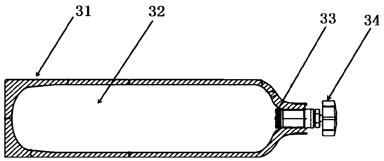
[0004] However, the volume of the hydrogen storage alloy expands by about 25% after hydrogen absorption, and the volume shrinks after dehydrogenation. Therefore, after multiple hydrogen absorption and desorption cycles, the hydrogen storage alloy will gradually pulverize. In the middle, it is very easy to flow with the flow of hydrogen gas, resulting in accumulation, so that the hydrogen storage device partially loses the gap, resulting in the deformation of the hydrogen storage tank during the hydrogen absorption and expansion of the hydrogen storage alloy, and even cracking and damage, causing safety accidents

Method used


Image

  • Copper-contained composite hydrogen storage alloy and preparation method for same, composite solid-state hydrogen storage tank, and hydrogen storage-discharge performance testing method
  • Copper-contained composite hydrogen storage alloy and preparation method for same, composite solid-state hydrogen storage tank, and hydrogen storage-discharge performance testing method
  • Copper-contained composite hydrogen storage alloy and preparation method for same, composite solid-state hydrogen storage tank, and hydrogen storage-discharge performance testing method

Examples


preparation example Construction

[0041] The preparation steps of hydrogen storage alloy powder: specifically include melting raw materials to prepare hydrogen storage alloy ingots, and then performing vacuum annealing homogenization treatment on the alloy ingots, the temperature of the melting is 1300 ° C ~ 1500 ° C The temperature of the homogenization treatment is 800-1150° C., and the annealing time is 5-10 hours; then, the annealed hydrogen storage alloy ingot is broken into small ingots, and ball milled to obtain the hydrogen storage alloy powder with a particle size of 75-300 μm.

[0042] Prepare copper material;

[0043] When the copper material is atomized copper powder, the atomized copper powder is spherical particles with a particle size of μm order, and the purity is preferably 99.85% to 99.9%; more preferably, the particle size of the atomized copper powder is 1-300 μm, It is further preferably 1-100 μm; when the copper material is electrolytic copper powder, the electrolytic copper powder is a d...

Embodiment 1

[0069] Prepare copper material: select 1-50 μm atomized copper powder as the copper material.

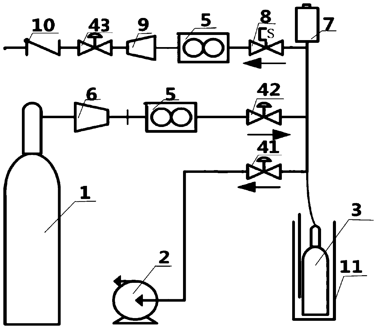
[0070]Preparation of composite hydrogen storage alloy powder: take 3200g of the above hydrogen storage alloy powder, 565g of atomized copper powder, the copper powder accounts for 15% of the total mass of the composite material, mix the two with a mixer, the mixing time is 2h, and then fill the composite material In the hydrogen storage tank, the composite hydrogen storage alloy powder accounts for about 80% of the volume of the hydrogen storage tank. Charge hydrogen and activate the composite hydrogen storage alloy powder in the hydrogen storage tank: install the hydrogen storage tank on the hydrogen storage tank hydrogen charging and activation treatment device, put the hydrogen storage tank in the heating jacket, and control the temperature at 90°C. Connect with the vacuum pump, open the ball valve and vacuum pump, pump out the air in the hydrogen storage tank for 6 hours, then f...

Embodiment 2

[0074] Prepare the copper material: select electrolytic copper powder with a particle size of 1-50 μm as the copper material.

[0075] Preparation of composite hydrogen storage alloy powder: take 3200g of the above hydrogen storage alloy powder, weigh 565g of electrolytic copper powder, copper powder accounts for 15% of the total mass of the composite material, mix the two with a mixer, and the mixing time is 2h, and then the composite material Filled into the hydrogen storage tank, the composite hydrogen storage alloy powder accounts for about 80% of the volume of the hydrogen storage tank.

[0076] Charge hydrogen and activate the composite hydrogen storage alloy powder in the hydrogen storage tank: install the hydrogen storage tank on the hydrogen storage tank hydrogen charging and activation treatment device, put the hydrogen storage tank in the heating jacket, and control the temperature at 90°C. Connect with the vacuum pump, open the ball valve and vacuum pump, pump out ...


PUM

PropertyMeasurementUnit
Sizeaaaaaaaaaa
Average particle sizeaaaaaaaaaa
The inside diameter ofaaaaaaaaaa

Abstract

The invention relates to copper-contained composite hydrogen storage alloy and a preparation method for the same as well as a composite solid-state hydrogen storage tank made of the copper-contained composite hydrogen storage alloy and a method for hydrogen storage performance testing of the composite solid-state hydrogen storage tank. The copper-contained composite hydrogen storage alloy is madeof, by mass, 85%-95% of hydrogen storage alloy powder and 5%-15% of a copper material. The preparation method for the copper-contained composite hydrogen storage alloy comprises the steps including astep for preparing hydrogen storage alloy powder, a step for preparing the carbon material, and a step for mixing the copper material and the hydrogen storage alloy powder to make carbon-contained composite hydrogen storage alloy. The composite solid-state hydrogen storage tank provided by the invention has the beneficial effects that under 50 DEG C, hydrogen is discharged at a hydrogen dischargeflow rate of 8L / Min; hydrogen discharge time can reach 53min; a hydrogen discharge amount can reach 424L; and the hydrogen discharge amount can reach 84.8% of a hydrogen storage amount of the hydrogenstorage tank.

Description

technical field [0001] The invention belongs to the technical field of preparation of hydrogen storage materials, and in particular relates to a copper-containing composite hydrogen storage alloy based on a copper material combined with a hydrogen storage alloy, a preparation method of a copper-containing composite hydrogen storage alloy, and a preparation method using the copper-containing composite hydrogen storage alloy. A composite solid-state hydrogen storage tank and a method for testing the hydrogen storage performance of the composite solid-state hydrogen storage tank. Background technique [0002] The depletion of fossil energy and the crisis of environmental pollution force human beings to develop renewable and clean energy. Hydrogen is a clean secondary energy and an ideal carrier of renewable primary energy. In the 1970s, General Motors of the United States put forward the concept of "hydrogen economy era" to describe the future where hydrogen will replace oil a...

Claims


Application Information

Patent Timeline
IPC IPC(8): B22F5/00B22F7/04F17C11/00G01N7/16H01M8/04082
CPCB22F7/04B22F5/00G01N7/16H01M8/04216F17C11/005F17C2201/0104F17C2201/058F17C2203/0646F17C2203/0648F17C2221/012F17C2225/0123F17C2265/01F17C2265/04F17C2250/0439F17C2250/043F17C2250/0473Y02P90/45Y02E60/32Y02E60/50
Inventor 武英原建光张宝阎有花周少雄
Owner JIANGSU JICUI ANTAI CHUANGMING ADVANCED ENERGY MATERIALS RES INST CO LTD
Learn More