Automatic preparation equipment for building putty

An automatic configuration, putty technology, applied in mixer accessories, mixers with rotary mixing devices, mixers, etc., can solve the problems of uneven mixing and large labor, and achieve the effect of easy operation and simple structure

Active Publication Date: 2020-02-14
CHINA NUCLEAR IND ZHONGYUAN CONSTR
View PDF8 Cites 2 Cited by
  • Summary
  • Abstract
  • Description
  • Claims
  • Application Information

AI Technical Summary

Problems solved by technology

[0004] In order to overcome the shortcomings that construction workers generally pour raw materials directly on the ground, and then pour water into them for manual mixing, which requires a large amount of labor and uneven mixing, the technical problem of the present invention is to provide a building that can mix evenly and can automatically mix ingredients. Putty auto-configures devices

Method used


Image

  • Automatic preparation equipment for building putty
  • Automatic preparation equipment for building putty
  • Automatic preparation equipment for building putty

Examples


Embodiment 1

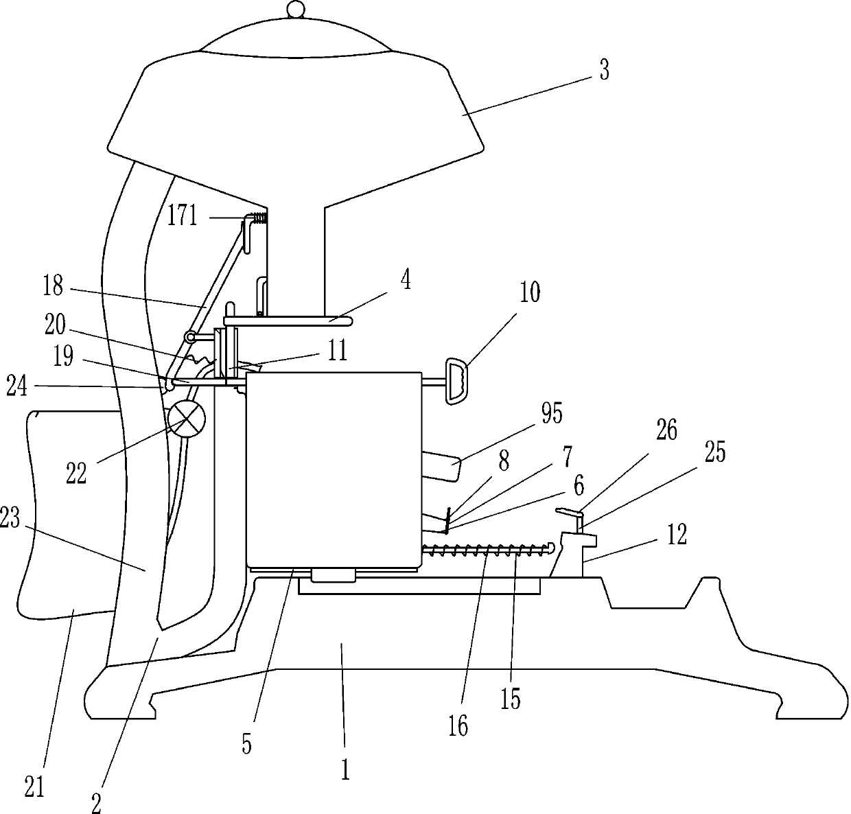
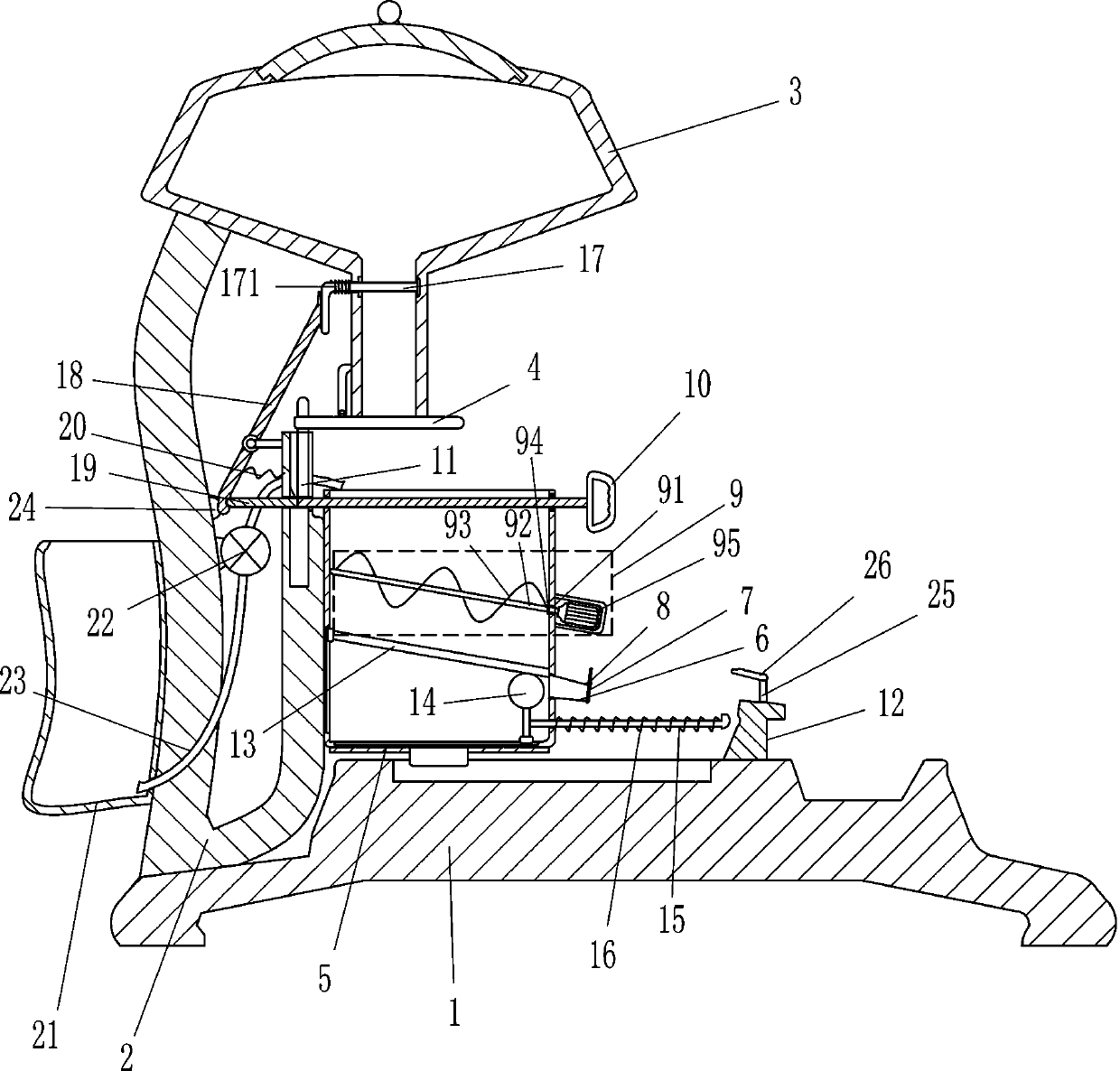
[0017] A building putty automatic configuration device such as Figure 1-3 As shown, it includes a support 1, a frame 2, a material box 3, a baffle plate 4, a mixing box 5, a torsion spring 51, a discharge pipe 6, a baffle plate 7, a first elastic member 8, a stirring device 9, and a pull rod 10. Toggle block 11, stop block 12, slide plate 13, top block 14, ejector rod 15 and second elastic member 16, frame 2 is set on the top of support 1, and material box is set on frame 2 through bolt connection 3. The number of the material box 3 is 2, and the baffle plate 4 is arranged on the discharge port of the material box 3 in a rotating manner, and a torsion spring 51 is arranged between the material baffle plate 4 and the discharge port, and the frame 2 slides A mixing box 5 is arranged on the mixing box 5, and a discharge pipe 6 is arranged on the mixing box 5. On the discharge pipe 6, a baffle plate 7 is rotatably arranged, and a first elastic member 8 is arranged between the baf...

Embodiment 2

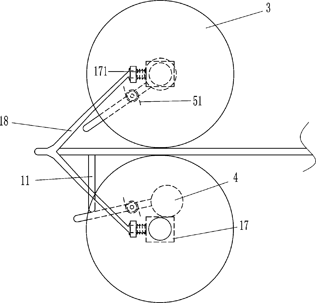
[0021] Such as Figure 1-3 As shown, on the basis of Embodiment 1, it also includes a moving plate 17, a third elastic member 171, a special-shaped rod 18, a connecting rod 19 and a fourth elastic member 20, and a sliding movement is provided on the outlet of the material box 3. Plate 17, a third elastic piece 171 is arranged between the moving plate 17 and the discharge port of the material box 3, and the third elastic piece 171 is a compression spring. On the left side of 17, a connecting rod 19 is arranged on the tie rod 10 by welding, and a fourth elastic member 20 is arranged between the special-shaped rod 18 and the frame 2, and the fourth elastic member 20 is a tension spring.

[0022] When quantitative feeding of gypsum powder and white cement is required, first push the pull rod 10 to the left, the pull rod 10 pushes the special-shaped rod 18 to move to the left through the connecting rod 19, the lower part of the special-shaped rod 18 swings to the left, and the four...


PUM


Abstract

The invention belongs to the technical field of building equipment, and particularly relates to automatic preparation equipment for building putty. The technical problem to be solved by the inventionis how to provide the building putty automatic preparation equipment which is uniform in stirring and capable of automatically preparing materials. The automatic preparation equipment comprises a support, a rack, two material tanks, material baffles, a mixing tank, torsion springs, a discharging pipe, a shielding plate, a first elastic piece, a stirring device, a pull rod, a stirring block and thelike, wherein the rack is arranged on the support, the two material tanks are arranged at the top of the support, the material baffles are rotatably arranged on discharge ports of the material tanks;each torsion spring is arranged between each material baffle and the corresponding discharge port. The effects of uniform stirring and automatic batching are achieved. Through driving the pull rod tomove leftwards, the mixing tank is located on the lower side of the material tanks; the pull rod abuts against a special-shaped rod, then the stirring block is driven to rotate, and quantitative feeding can be achieved.

Description

technical field [0001] The invention belongs to the technical field of construction equipment, and in particular relates to an automatic configuration equipment for construction putty. Background technique [0002] Putty is a decorative material for leveling the surface of the wall. It is a thick paste paint and an indispensable product before the paint is painted. It is applied on the primer or directly on the object to remove uneven defects on the surface of the object to be coated. The support of the government and the continuous improvement of people's requirements for decoration materials make the development of putty powder continue to improve. , in the next few years, water-resistant putty will occupy more markets, and the proportion of functional putty powder in water-resistant putty will increase. The flexible putty powder for exterior walls with super water resistance has the ability to absorb harmful gases, Interior wall putty powder that releases negative ions, ...

Claims


Application Information

Patent Timeline
IPC IPC(8): B01F7/08B01F15/02
CPCB01F27/72B01F35/751B01F2101/30
Inventor 不公告发明人
Owner CHINA NUCLEAR IND ZHONGYUAN CONSTR
Why Eureka
Try Eureka