Induction-heating cooker and sensor unit
An induction heating and cooker technology, applied in induction heating, induction heating devices, electric/magnetic/electromagnetic heating, etc., can solve the problems of decreased precision, unstable output, and decreased accuracy of cooking container temperature detection, and achieves suppression of overlapping, Effect of simple structure and improved temperature detection accuracy
- Summary
- Abstract
- Description
- Claims
- Application Information
AI Technical Summary
Problems solved by technology
Method used
Image

Examples
Embodiment approach 1
[0063] (Structure of induction heating cooker)
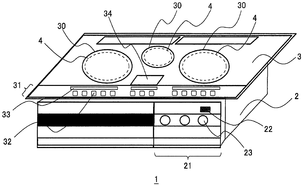
[0064] First, the configuration of the induction heating cooker 1 will be described. figure 1 It is a schematic perspective view of the induction heating cooker 1 in Embodiment 1. Such as figure 1 As shown, the induction heating cooker 1 includes a main body 2 and a top plate 3 arranged on the upper surface of the main body 2 . A front surface operation unit 21 is provided on the front surface of the main body 2 . A power switch 22 for turning on / off the power supply of the induction heating cooker 1 and a plurality of operation dials 23 for adjusting heating power are arranged on the front surface operation part 21 .
[0065] The top plate 3 is composed of, for example, a heat-resistant glass plate and a metal frame. A plurality of (three in this embodiment) circular heating ports 30 indicating heating regions are provided on the upper surface of the top plate 3 by printing or the like. Cooking containers 100 such as pots ...
Deformed example 1-1
[0133] Figure 16 is a plan view of the non-contact temperature sensor 7A in Modification 1-1, Figure 17 so Figure 16 A longitudinal sectional view obtained by cutting the non-contact temperature sensor 7A in Modification 1-1 along line A-A. In addition, in Figure 16 and Figure 17 in, right with Figure 10 and Figure 11 The same reference signs are assigned to the same constituent elements as shown.
[0134] Such as Figure 16 and Figure 17 As shown, magnetic circuit forming mechanism 200A in proximity temperature sensor 7A of this modified example has a larger area than substrate 212 of infrared sensor unit 210 in plan view, and is arranged to cover substrate 212 . In addition, the length of the side parallel to the direction of the magnetic flux passing through the substrate 212 may be longer than the length of the side parallel to the direction of the magnetic flux of the substrate 212 in the magnetic path forming mechanism 200A. In addition, an opening 201 t...
Deformed example 1-2
[0137] Figure 18 is a plan view of the non-contact temperature sensor 7B in Modification 1-2, Figure 19 It is a figure explaining the guidance of the magnetic flux by the magnetic path formation mechanism of the modification 1-2. In addition, in Figure 18 and Figure 19 in, right with Figure 10 The same reference signs are assigned to the same constituent elements as shown.
[0138] Such as Figure 18 and Figure 19 As shown, the non-contact temperature sensor 7B of this modified example includes a first magnetic path forming mechanism 200Ba and a second magnetic path forming mechanism 200Bb facing each other across the opening 231 on the upper surface of the upper case 230 . The first magnetic path forming mechanism 200Ba and the second magnetic path forming mechanism 200Bb each have a rectangular flat plate shape and are arranged in parallel to the direction of the magnetic flux generated in the proximity temperature sensor 7B. In addition, the first magnetic path...
PUM
| Property | Measurement | Unit |
|---|---|---|
| thermal resistance | aaaaa | aaaaa |
| Curie point | aaaaa | aaaaa |
| transmittivity | aaaaa | aaaaa |
Abstract
Description
Claims
Application Information
 - R&D
- Intellectual Property
- Life Sciences
- Materials
- Tech Scout
- Unparalleled Data Quality
- Higher Quality Content
- 60% Fewer Hallucinations
Browse by: Latest US Patents, China's latest patents, Technical Efficacy Thesaurus, Application Domain, Technology Topic, Popular Technical Reports.
© 2025 PatSnap. All rights reserved.Legal|Privacy policy|Modern Slavery Act Transparency Statement|Sitemap|About US| Contact US: help@patsnap.com