an optical receiver

An optical receiver and interface technology, applied in the field of optical communication, can solve the problems of high cost and high device cost, and achieve the effect of reducing device cost, reducing cost, and compensating for the degradation of received signals

Active Publication Date: 2021-05-28
HUAWEI TECH CO LTD
View PDF3 Cites 0 Cited by
  • Summary
  • Abstract
  • Description
  • Claims
  • Application Information

AI Technical Summary

Problems solved by technology

[0004] The embodiment of the present application provides an optical receiver, which uses a low-speed APD to receive high-speed signals, and solves the problem that the cost of the entire device is too high due to the high cost of the high-speed APD

Method used


Image

  • an optical receiver
  • an optical receiver
  • an optical receiver

Examples


Embodiment Construction

[0045] The technical solutions in the embodiments of the present application will be described below with reference to the drawings in the embodiments of the present application.

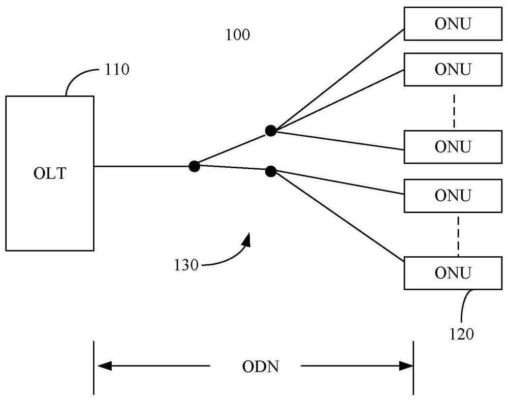
[0046] see figure 1, which is a schematic structural diagram of a 10G PON system to which an ONU or (Optical Line Terminal, OLT) with an optical receiver provided in an embodiment of the present application can be applied. The 10G PON system 100 includes at least one OLT 110 , multiple ONUs 120 and an Optical Distribution Network 130 (Optical Distribution Network, ODN). Wherein, the OLT 110 is connected to multiple ONUs 120 in a point-to-multipoint manner through the ODN 130 . Wherein, the direction from OLT 110 to ONU 120 is defined as the downlink direction, and the direction from ONU 120 to OLT 110 is defined as the uplink direction.

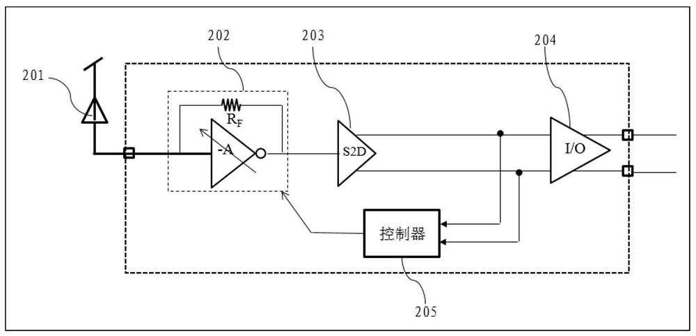
[0047] An embodiment of the present application provides an optical receiver 200, which can be applied to an ONU of a 10G PON system or a higher rate PON system,...


PUM


Abstract

An optical receiver (200), comprising: a photodetector (201), a transimpedance amplifier circuit (202), a single-end-differential converter (203), an I/O interface (204) and a controller (205). The photodetector (201) is used to convert the received optical signal into a current signal, and its bandwidth is lower than the bandwidth requirement of system transmission; the transimpedance amplifier circuit (202) is used to receive the current signal and the first control signal, according to the first The control signal performs transimpedance gain on the current signal to obtain a voltage signal, and the frequency response value of the current signal in the first bandwidth at any frequency not lower than the upper limit cut-off frequency of the photodetector (201) is higher than that of the photodetector (201) The frequency response value within the bandwidth; the single-end-differential converter (203) is used to convert the voltage signal into a differential voltage signal; the I/O interface (204) is used to output the differential voltage signal; the controller (205) is used to The voltage signal is used to generate a second control signal for controlling the transimpedance gain of the current signal. The optical receiver realizes the purpose of reducing the cost under the condition of ensuring the quality of the received signal.

Description

technical field [0001] The present application relates to the field of optical communication, in particular to an optical receiver with high-frequency peak gain. Background technique [0002] 10G passive optical network (Passive Optical Network, PON) technology and products have been prepared and entered the stage of large-scale deployment. In 10G PON, the cost of optical network unit (Optical Network Unit, ONU) becomes the issue of whether mass deployment in the future A key issue for 10G PON is cost reduction. However, the Bi-directional Optical Sub-Assembly On Board (BOB) technology widely used in Gigabit Passive Optical Network (GPON) can be used in 10G PON to reduce packaging costs, so , the cost of the device itself has become the key to further cost reduction. [0003] In the ONU of 10G PON, 10G Avalanche Photo-Detector (APD) is the highest rate optical device, and it also accounts for the highest proportion of cost. Therefore, reducing the cost of APD becomes the k...

Claims


Application Information

Patent Timeline
Patent Type & Authority Patents(China)
IPC IPC(8): H04B10/69
CPCC22C38/52C22C38/44C22C38/54C22C38/005C22C33/02B22F3/10H04B10/693H04B10/69H04B10/6971H04B10/695H04B10/6931H04Q11/0067H04Q11/0071
Inventor 付生猛熊宇满江伟王成艳曾小飞曾理
Owner HUAWEI TECH CO LTD
Why Eureka
Try Eureka