Electronic device and method for wireless communication, and computer readable storage medium
A technology for wireless communication and electronic equipment, applied in computer-readable storage media, electronic equipment for wireless communication, and transmission technology in unlicensed frequency bands, can solve problems such as inappropriateness, reduce load, improve efficiency, and improve spectrum resources. The effect of utilization
- Summary
- Abstract
- Description
- Claims
- Application Information
AI Technical Summary
Problems solved by technology
Method used
Image
Examples
no. 1 example
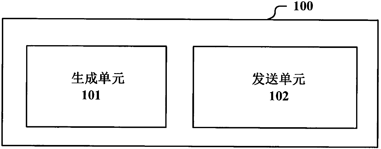
[0053] figure 1 Shows a block diagram of functional modules of an electronic device 100 for wireless communication according to an embodiment of the present application, as shown in figure 1 As shown, the electronic device 100 includes: a generation unit 101, in the case that the UE successfully accesses an unlicensed frequency band, generates an indication indicating whether to allow the COT of the UE to be shared with other UEs; and a sending unit 102 configured to The indication is sent to the base station or other UEs.
[0054] Wherein, the generating unit 101 and the sending unit 102 may be implemented by one or more processing circuits, and the processing circuits may be implemented as a chip, for example. And, it should be understood, figure 1 Each functional unit in the device shown in is only a logical module divided according to the specific function it realizes, and is not used to limit the specific implementation. The same applies to examples of other electronic...
no. 2 example
[0063] figure 2 Shows a block diagram of functional modules of an electronic device 200 for wireless communication according to another embodiment of the present application, as shown in figure 2 As shown, the electronic device 200 includes: an obtaining unit 201 configured to obtain an indication indicating whether other UEs are allowed to share the COT of the UE from a UE that has successfully accessed an unlicensed frequency band; and a scheduling unit 202 configured to The indication indicates that when other UEs are allowed to share the COT of the UE, the spectrum resource accessed by the UE is scheduled for other UEs within the COT.
[0064] Similarly, the acquiring unit 201 and the scheduling unit 202 may be implemented by one or more processing circuits, and the processing circuits may be implemented as a chip, for example. And, it should be understood, figure 2 Each functional unit in the device shown in is only a logical module divided according to the specific ...
no. 3 example
[0075] Figure 6 Shows a block diagram of functional modules of an electronic device 300 for wireless communication according to another embodiment of the present application, as shown in Figure 6 As shown, the electronic device 300 includes: a generating unit 301 configured to generate an indication indicating whether multiple switching points are supported in the MCOT when the UE successfully accesses the unlicensed frequency band, wherein the switching point represents uplink transmission and downlink switching between transmissions; and a sending unit 302 configured to include the indication in UCI for sending to the base station.
[0076] Similarly, the generating unit 301 and the sending unit 302 may be implemented by one or more processing circuits, and the processing circuits may be implemented as a chip, for example. For example, the electronic device 300 may be disposed on the UE side or communicably connected to the UE.
[0077] Here, more flexible transmission c...
PUM
 Abstract
Description
Claims
Application Information
 - R&D
- Intellectual Property
- Life Sciences
- Materials
- Tech Scout
- Unparalleled Data Quality
- Higher Quality Content
- 60% Fewer Hallucinations
Browse by: Latest US Patents, China's latest patents, Technical Efficacy Thesaurus, Application Domain, Technology Topic, Popular Technical Reports.
© 2025 PatSnap. All rights reserved.Legal|Privacy policy|Modern Slavery Act Transparency Statement|Sitemap|About US| Contact US: help@patsnap.com


