A remote diagnosis device for train running faults
A technology for running faults and remote diagnosis, applied in the direction of railway vehicle testing, etc., can solve the problems of inconvenient maintenance of fault diagnosis devices, strong vibration force of vehicle chassis, affecting detection accuracy, etc. Effect
- Summary
- Abstract
- Description
- Claims
- Application Information
AI Technical Summary
Problems solved by technology
Method used
Image
Examples
Embodiment 1
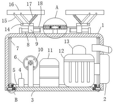
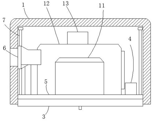
[0025] A remote diagnosis device for train running faults, comprising a housing 1, a horizontal plate 3, a sensor group 10 fixed on the horizontal plate 3, a signal processing and transmission device 13, a central processing system 11, a data input and output interface device 4 and a vehicle The image acquisition device 12, the upper end of the housing 1 is fixedly connected with two fixed blocks, and the opposite sides of the two fixed blocks are fixedly connected with a rectangular rod 8 horizontally, and a connecting mechanism is provided on the rod wall of the rectangular rod 8, and the housing 1 The upper end of the upper end is fixedly connected with a horizontal tube 19, and a buffer mechanism is arranged in the horizontal tube 19. The buffer mechanism is connected with the connecting mechanism on the two rectangular rods 8. The connecting mechanism includes a rectangular tube 9 slidingly sleeved on the rectangular rod 8, and the rectangular tube The upper end of 9 is fi...
Embodiment 2
[0027] Embodiment 2: the difference based on Embodiment 1 is;
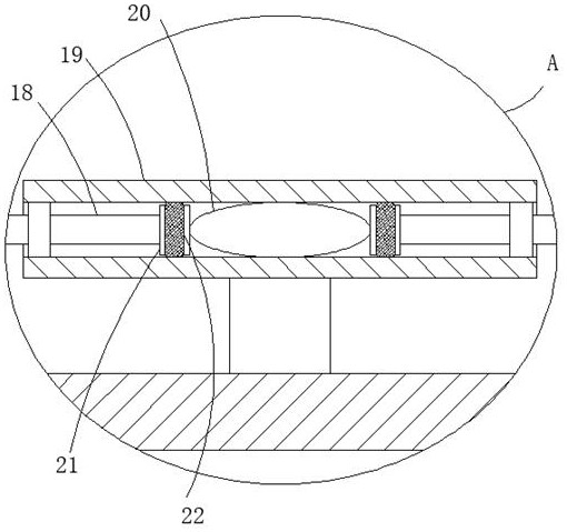
[0028]The buffer mechanism includes two cross bars 18 that are movably socketed in the cross tube 19, and the opposite ends of the two cross bars 18 are fixedly connected with a piston 21, and the side wall of the piston 21 is fixedly connected with a sealing ring 22, and the cross bar 18 is away from the One end of the piston 21 extends to the outside of the cross tube 19 and is fixedly connected to one side of the rectangular tube 9. The air bag 20 with an oval structure is fixedly connected in the cross tube 19. The piston 21 is connected in contact.
[0029] The present invention is provided with a buffer mechanism. When in use, when the transmission rod 15 in the connecting mechanism swings, the mounting plate 16, the connection plate 14 and the two transmission rods 15 form a rhombus together, and when the tension spring 17 pulls the transmission rod 15 to swing , the rectangular tube 9 below the connecting...
Embodiment 3
[0030] Embodiment 3: the difference based on embodiment 1 is;
[0031] The fixing mechanism includes a fixing rod 23 slidingly sleeved in the cylindrical groove. One end of the fixing rod 23 extends into the fixing groove and has an inclined surface. The other end of the fixing rod 23 is fixedly connected with a first spring 27, and the first spring 27 is away from the One end of the fixed rod 23 is fixedly connected with one side of the cylindrical groove, and the lower side of the horizontal plate 3 is provided with a strip-shaped through hole communicating with the cylindrical groove, and the strip-shaped through-hole is slidably connected with a brake lever 28. One end passes through the strip-shaped through hole and is fixedly connected with the rod wall of the fixed rod 23. The inner walls of the opposite sides of the rectangular frame 5 are fixedly connected with sliding sleeves 25, and the two sliding sleeves 25 are slidingly sleeved with the top of the T-shaped structu...
PUM
 Abstract
Description
Claims
Application Information
 - R&D
- Intellectual Property
- Life Sciences
- Materials
- Tech Scout
- Unparalleled Data Quality
- Higher Quality Content
- 60% Fewer Hallucinations
Browse by: Latest US Patents, China's latest patents, Technical Efficacy Thesaurus, Application Domain, Technology Topic, Popular Technical Reports.
© 2025 PatSnap. All rights reserved.Legal|Privacy policy|Modern Slavery Act Transparency Statement|Sitemap|About US| Contact US: help@patsnap.com


