Vertical cooling kiln and mineral aggregate cooling and waste heat recovery method

A technology of ore material and cooling air, which is applied in the field of vertical cooling kiln and ore material cooling and waste heat recovery, can solve the problem of the waste heat recovery efficiency that the ore material cannot be uniformly cooled, and achieve the effect of improving waste heat recovery efficiency, efficient recovery and realizing waste heat.

Pending Publication Date: 2020-02-11
SHEN KAN QINHUANGDAO GENERAL ENG DESIGN & RES INST CORP MCC
View PDF0 Cites 2 Cited by
  • Summary
  • Abstract
  • Description
  • Claims
  • Application Information

AI Technical Summary

Problems solved by technology

[0007] The second purpose of the present invention is to provide a method for mineral material cooling and waste heat recovery, so as to alleviate the technical problems in the prior art that the mineral material cannot be cooled uniformly and the waste heat recovery efficiency is low due to uneven air supply

Method used


Image

  • Vertical cooling kiln and mineral aggregate cooling and waste heat recovery method
  • Vertical cooling kiln and mineral aggregate cooling and waste heat recovery method
  • Vertical cooling kiln and mineral aggregate cooling and waste heat recovery method

Examples


Embodiment 1

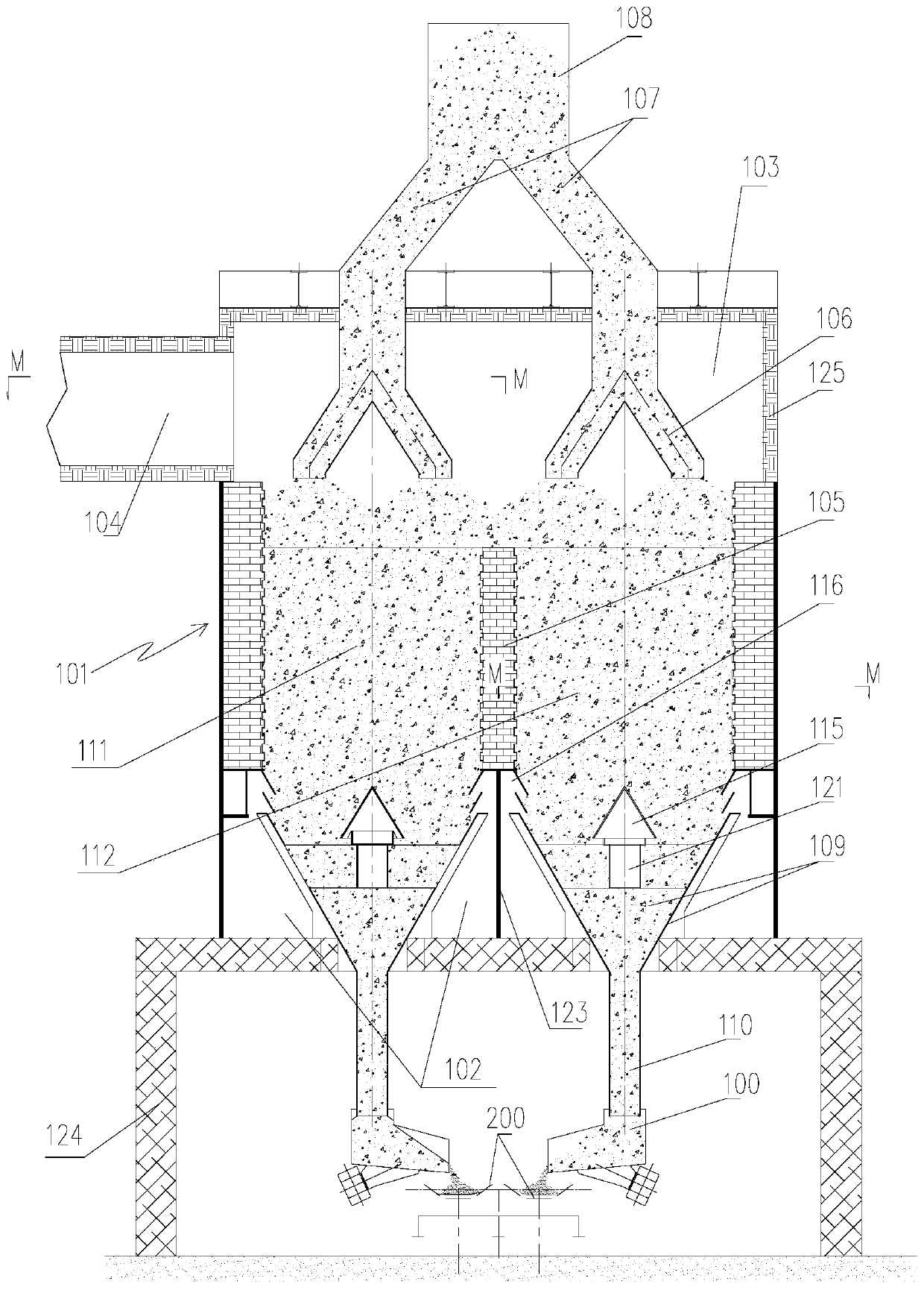
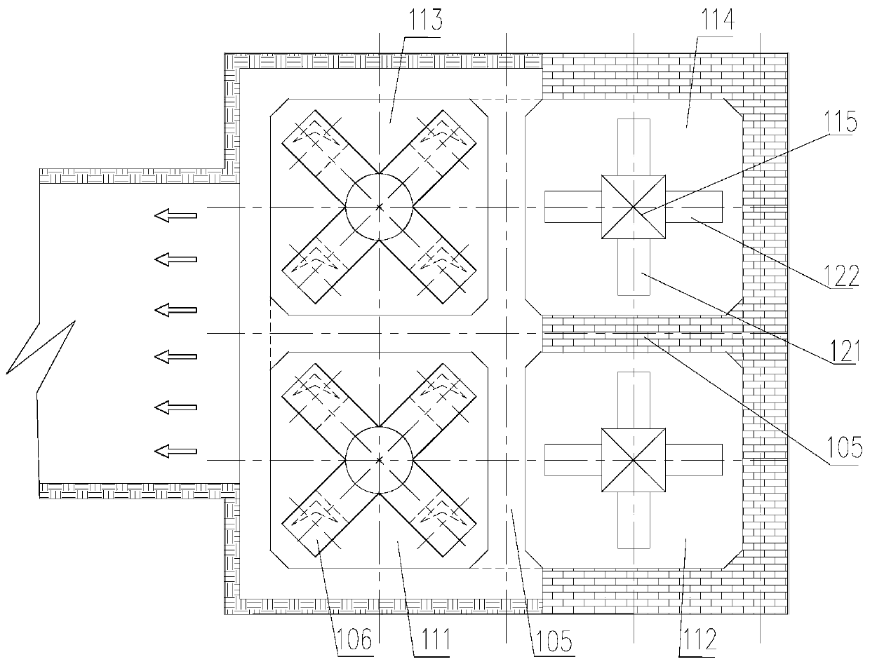
[0039] see Figure 1 to Figure 5 As shown, the present embodiment provides a vertical cooling kiln, comprising:

[0040] The kiln body 101, the bottom of the kiln body 101 is a cooling air supply chamber, the top of the kiln body 101 is a hot air concentration chamber 103, at least one cooling unit cavity is arranged between the cooling air supply chamber and the hot air concentration chamber 103 The cooling unit chamber is used to communicate with the material receiving port of the discharge machine 100; the cooling air supply chamber is used to provide cooling air to the cooling unit chamber, and the hot air concentration chamber 103 is used to communicate with the hot air delivery channel 104 ;

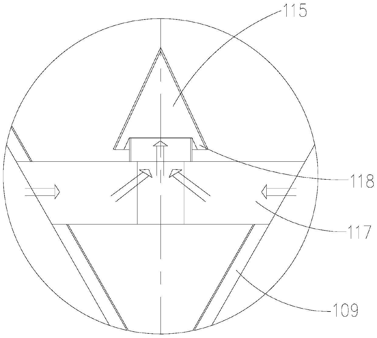
[0041]The inner ring air supply device, the inner ring air inlet 117 of the inner ring air supply device communicates with the cooling air supply chamber, and the inner ring air outlet 118 of the inner ring air supply device communicates with the cooling unit chamber, for making t...

Embodiment 2

[0081] The embodiment of the present invention provides a method for mineral material cooling and waste heat recovery, which is carried out by using the vertical cooling kiln provided by the present invention, wherein the number of cooling unit chambers is one, and the method includes the following steps:

[0082] Fill the cooling unit chamber with mineral material;

[0083] Supply cooling air to the cooling unit chamber;

[0084] Continuous or intermittent discharge of mineral material in the chamber of the cooling unit.

[0085] The embodiment of the present invention also provides a method for mineral material cooling and waste heat recovery, which is carried out by using the vertical cooling kiln provided by the present invention, wherein the number of cooling unit chambers is multiple, and the method includes the following steps:

[0086] Fill the cooling unit chamber with mineral material;

[0087] Supply cooling air to the cooling unit chamber;

[0088] The mineral m...


PUM


Abstract

The invention relates to the technical field of sinter cooling devices, in particular to a vertical cooling kiln and a mineral aggregate cooling and waste heat recovery method. The vertical cooling kiln comprises a kiln body, an inner ring air supply device, and an outer ring air supply device, wherein a cooling air supply chamber is arranged at the bottom of the kiln body, a hot air concentrationchamber is arranged at the top of the kiln body, and at least one cooling unit chamber is arranged between the cooling air supply chamber and the hot air concentration chamber; the cooling air supplychamber is used for providing cooling air to the cooling unit chambers, and the hot air concentration chamber is used for communicating with a hot air delivery channel; the inner ring air supply device is used for making the cooling air flow to the periphery from the centers of the cooling unit chambers; and an outer ring air inlet of the outer ring air supply device communicates with the coolingair supply chamber, and the outer ring air supply device is used for making the cooling air flow from the periphery of the cooling unit chambers to the centers. According to the vertical cooling kilnand the method, the uniformity of air supply into the cooling unit chambers can be improved, the uniform cooling of a mineral aggregate is realized, and the waste heat recovery efficiency is improved.

Description

technical field [0001] The invention relates to the technical field of sinter cooling devices, in particular to a vertical cooling kiln and a mineral material cooling and waste heat recovery method. Background technique [0002] The cooling process of the sinter vertical cooling kiln is to continuously (or intermittently) put the hot crushed sinter from the top of the vertical cooling kiln into a closed vertical container (kiln chamber) for cooling, from the kiln A sinter cooling process that discharges cold ore continuously (or intermittently with a certain rhythm) from the bottom of the chamber. [0003] The sintered ore that enters the kiln is filled to a specific height of the kiln in a natural accumulation state (determined by the structure of the distributor), and when the bottom of the kiln discharges the ore continuously (or intermittently with a certain rhythm), the sintering in the kiln Under the action of its own weight, the mineral material flows from top to bot...

Claims


Application Information

Patent Timeline
Patent Type & Authority Applications(China)
IPC IPC(8): F27B1/24F27B1/22F27D17/00
CPCF27B1/22F27B1/24F27D17/004
Inventor 梁长林杨亮杜慧卿陈冲刘保平王伟石小旭
Owner SHEN KAN QINHUANGDAO GENERAL ENG DESIGN & RES INST CORP MCC
Why Eureka
Try Eureka