Clamping structure of thin-walled piece, clamping method of thin-walled piece and application of clamping structure of thin-walled piece

A thin-walled parts and clamping technology, which is applied in the field of parts processing, can solve the problems of uneven stress on various parts of the surface of thin-walled parts, easy vibration and deformation, and easy deformation during processing, etc., to achieve high industrial application prospects, The effect of convenient operation and easy clamping

Pending Publication Date: 2020-02-11
KONFOONG MATERIALS INTERNATIONAL CO LTD
View PDF3 Cites 3 Cited by
  • Summary
  • Abstract
  • Description
  • Claims
  • Application Information

AI Technical Summary

Problems solved by technology

[0003] CN106216724A discloses a fast turning fixture for thin-walled parts with stepped soft claws, which alleviates the problem of insufficient clamping force of the original fixture to a certain extent, but the fixture still clamps thin-walled parts from all sides method, it is easy to cause deformation of thin-walled parts during processing
[0004] CN103447851A discloses an anti-deformation fixture for lathe processing of annular thin-walled parts. The fixture uses the circumference of the fixture body to make the inner peripheral surface of the thin-walled part to realize the clamping of the thin-walled part. However, this method is only applicable to round Thin-walled parts with shaped structure, and the clamping area is small, the workpiece is still prone to vibration and deformation during processing
[0005] CN109333092A discloses a fixture for annular thin-walled parts. The fixture uses three pressing blocks to clamp the annular thin-walled parts. Uneven, prone to deformation during processing

Method used


Image

  • Clamping structure of thin-walled piece, clamping method of thin-walled piece and application of clamping structure of thin-walled piece
  • Clamping structure of thin-walled piece, clamping method of thin-walled piece and application of clamping structure of thin-walled piece
  • Clamping structure of thin-walled piece, clamping method of thin-walled piece and application of clamping structure of thin-walled piece

Examples


Embodiment 1

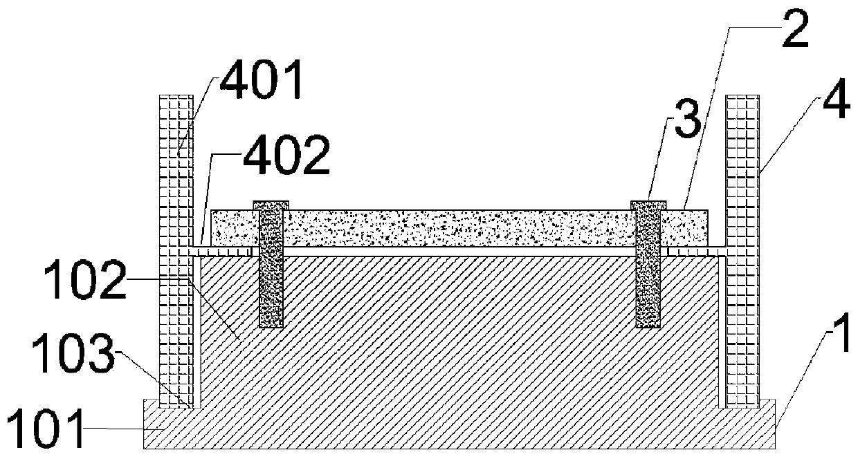
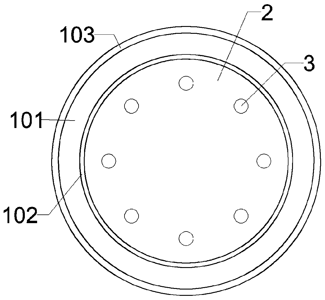
[0076] This embodiment provides a clamping structure for thin-walled parts, such as figure 1 with figure 2 As shown, the clamping structure includes a base 1 and a circular cover plate 2;

[0077] The abutment 1 includes a base 101 and a boss 102 protruding upward from the center of the base. The diameter of the boss 102 is 249.95 mm, the height of the boss 102 is 49.6 mm, the diameter of the base 101 is 260 mm, and the edge is provided with 8.05 mm wide, 0.4 mm deep groove 103, the upper surface of the boss 102 is provided with 8 boss holes (not shown) equiangularly distributed, the radial distance from the center of the boss hole to the circumference of the boss 102 is 16.15mm, so The thickness of the base 101 is 20mm, and the material of the abutment 1 is stainless steel;

[0078] The cover plate 2 is arranged on the boss 102, the thickness of the cover plate 2 is 5 mm, the diameter of the cover plate 2 is 249.8 mm, and the cover plate 2 is provided with 8 cover plates t...

Embodiment 2

[0082] This embodiment provides a clamping structure for thin-walled parts, the clamping structure includes a base and a circular cover plate;

[0083] The abutment includes a base and a boss protruding upward from the center of the base. The diameter of the boss is 49.9 mm, the height of the boss is 39.7 mm, the diameter of the base is 55 mm, and the edge is provided with a groove with a width of 3.1 mm and a depth of 0.3 mm. The upper surface of the boss is provided with three boss holes equiangularly distributed, the radial distance from the center of the boss hole to the circumference of the boss is 14.9 mm, the thickness of the base is 10 mm, and the material of the base is aluminum alloy 6061;

[0084] Described cover plate is arranged on the boss, and the thickness of cover plate is 15mm, and the diameter of cover plate is 49mm, and cover plate is provided with 3 cover plate holes that run through cover plate and is equiangular distribution, the circle center of cover p...

Embodiment 3

[0088] This embodiment provides a clamping structure for thin-walled parts. The clamping structure is the same as that of Embodiment 1 except that the circular cover plate is replaced by a circular cover plate.

[0089] The clamping structure specifically includes: an abutment and an annular cover plate;

[0090] The abutment includes a base and a boss protruding upward from the center of the base. The diameter of the boss is 249.95 mm, the height of the boss is 49.6 mm, the diameter of the base is 260 mm, and the edge is provided with a groove of 8.05 mm wide and 0.4 mm deep. The upper surface of the boss is provided with 8 boss holes (not shown) equiangularly distributed, the radial distance from the center of the boss hole to the circumference of the boss is 16.15mm, the thickness of the base is 20mm, the The abutment is made of stainless steel;

[0091] The cover plate is arranged on the boss, the thickness of the cover plate is 5mm, the outer diameter of the cover plate ...


PUM


Abstract

The invention provides a clamping structure of a thin-walled piece. The clamping structure is provided with a base platform and a cover plate. The base platform comprises a base and a boss protrudingupwards from the center of the base. The boss is fixed to the cover plate through a fixing device penetrating through the cover plate to extend into the boss. Clamping of the thin-walled piece is achieved in a vertical clamping manner, the thin-walled piece cannot vibrate in the machining process, and therefore the flatness of the machined thin-walled piece can be guaranteed. By the adoption of the clamping method of the clamping structure of the thin-walled piece, the thin-walled piece is arranged between the boss and the cover plate, rapid clamping can be achieved, the thin-walled piece canbe effectively prevented from twisting and deforming in the machining process, and machining requirements of semiconductor parts can be better met.

Description

technical field [0001] The invention relates to the technical field of parts processing, in particular to a clamping structure of a thin-walled part, a clamping method and application of the thin-walled part. Background technique [0002] Thin-walled parts: Because of the characteristics of light weight, material saving, and compact structure, thin-walled parts have been increasingly widely used in various industrial sectors. However, the processing of thin-walled parts is more difficult, because the thin-walled parts have poor rigidity and weak strength, and are easily deformed during processing, which makes it difficult to guarantee the processing quality of the parts. There are many factors that affect the machining accuracy of thin-walled parts, but they can be summarized in the following three aspects: (1) Forced deformation; (2) Thermal deformation; (3) Vibration deformation. [0003] CN106216724A discloses a fast turning fixture for thin-walled parts with stepped sof...

Claims


Application Information

Patent Timeline
Patent Type & Authority Applications(China)
IPC IPC(8): B23Q3/06
CPCB23Q3/065
Inventor 姚力军潘杰边逸军王学泽周建军
Owner KONFOONG MATERIALS INTERNATIONAL CO LTD
Why Eureka
Try Eureka