
A Precise Positioning Method for Electrolytic Forming of Thin-walled Shells

A precise positioning, thin-walled shell technology, applied in electric machining equipment, electrochemical machining equipment, accessories, etc., can solve the problem of positioning error sensitivity, achieve high-precision positioning, improve positioning accuracy and reliability, reduce The effect of positioning adjustment time

Active Publication Date: 2020-09-08
AVIC BEIJING AERONAUTICAL MFG TECH RES INST
View PDF12 Cites 0 Cited by
  • Summary
  • Abstract
  • Description
  • Claims
  • Application Information

AI Technical Summary

Problems solved by technology

However, since the special-shaped cavity on the surface of the thin-walled shell is located on the rotating surface, and the surface of the machining electrode must adapt to the machined part, the machining result is extremely sensitive to positioning errors

Method used


Image

  • A Precise Positioning Method for Electrolytic Forming of Thin-walled Shells
  • A Precise Positioning Method for Electrolytic Forming of Thin-walled Shells

Examples


Embodiment 1

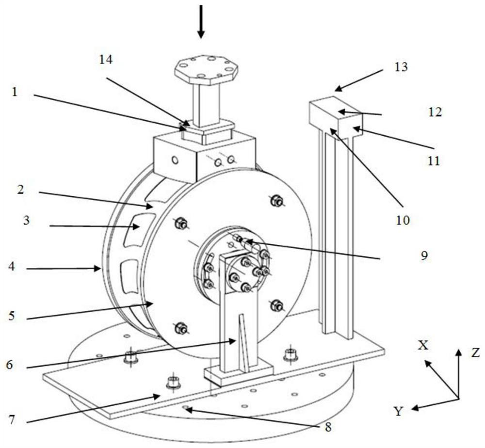
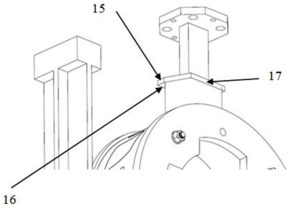
[0044] Example 1: Before electrolytic machining, the U18 reference plane 15 of the forming electrode 1 is brought into contact with the XZ reference plane 10 to obtain the Y coordinate value C of the machine tool 2 is 305.32; make the V19 reference plane 16 of the forming electrode 1 contact the XY reference plane 12, and obtain the Z coordinate value C of the machine tool 3 is 311.05; the W20 reference plane 17 of the forming electrode 1 is in contact with the YZ reference plane 11 to obtain the X coordinate value C of the machine tool 1 for 258.61. Then through the conversion formula X=C 1 -B 1 -A 1 ;y=C 2 -B 2 -A 2 ;z=C 3 -(B 3 / 2-T), that is, X=C 1 -B 1 -A 1 =258.61-20-100=138.61; y=C 2 -B 2 -A 2 =305.32-30-200=75.32; z=C 3 -(B 3 / 2-T)=311.05-(40-2-0.2)=291.25 The converted machine tool coordinates (138.61, 75.32, 291.25) are the initial machining coordinates of electrolytic machining.


PUM

PropertyMeasurementUnit
radiusaaaaaaaaaa

Abstract

The invention relates to an accurate positioning device for electrolytic forming of a thin-wall housing. The accurate positioning device comprises a clamping tool used for fixing a workpiece and a positioning device used for positioning a forming electrode, wherein the clamping tool comprises a base mounted on a machine tool workbench; a support is arranged on the base in the vertical direction; an indexing plate used for fixing the workpiece is rotationally arranged at the upper end of the support; an indexing pin used for limiting rotation of the indexing plate is arranged between the indexing plate and the support; the clamping tool further comprises a detachable pressing ring used for clamping the workpiece to the indexing plate; and the positioning device comprises a three-way positioning datum plane on the forming electrode and a three-way positioning block vertically and fixedly arranged on the base. According to the accurate positioning device, the forming electrode integratinga machining profile and a tool setting datum and the permanent three-way tool setting positioning block are adopted, accurate positioning of the forming electrode is achieved, and the problem that the positioning error is large due to the links of assembling, adjusting and the like between the electrode and the workpiece is solved.

Description

technical field [0001] The invention relates to the technical field of electrolytic machining technology, in particular to a precise positioning method for electrolytic forming of a thin-walled shell. Background technique [0002] Electrolytic machining is a special processing method that uses the principle of electrochemical anodic dissolution to achieve metal removal. It has technical advantages such as high processing efficiency, no consumption of tool electrodes, no stress during processing, and good surface integrity. It is suitable for various difficult-to-machine metal materials (Stainless steel, titanium alloy, high-temperature heat-resistant alloy) high-efficiency and precision machining, especially suitable for batch production and processing of parts that remove a large amount of material efficiently and processing of various three-dimensional complex shapes. [0003] In electrolytic machining, the tool electrode is the cathode and the workpiece is the anode. The...

Claims


Application Information

Patent Timeline
Patent Type & Authority Patents(China)
IPC IPC(8): B23H9/00B23H11/00B23H3/00
CPCB23H3/00B23H9/00B23H11/00B23H11/003
Inventor 黄明涛程小元张明岐刘萌
Owner AVIC BEIJING AERONAUTICAL MFG TECH RES INST
Learn More