Filtration device for oil production well hot washing liquid

A technology for liquid filtration and oil production wells, which is applied in the field of hot washing liquid filtration devices for oil production wells, can solve problems such as troublesome cleaning, influence oil well production, oil well pump stuck, etc., and achieve the effect of rapid cleaning

Active Publication Date: 2022-02-18
孙雨飞
View PDF12 Cites 0 Cited by
  • Summary
  • Abstract
  • Description
  • Claims
  • Application Information

AI Technical Summary

Problems solved by technology

[0005] But above-mentioned technical scheme still has many shortcomings when practical application;
[0006] 1. Due to the simple structure of the device, the formation sand, scale, cement block and other sundries in the flushing fluid are only intercepted by the filter cartridge, and the retained formation sand, scale, cement block and other sundries are accumulated in the filter cartridge for a long time After the accumulation of time, the flow of the well flushing fluid is not smooth and must be cleaned in time. It is necessary to remove the washing fluid filter device and take out the filter cartridge to clean up. The cleaning is troublesome and delays the well cleaning period;
[0007] 2. Due to the small particle diameter of the formation sand, the particles of the formation sand easily pass through the aperture of the filter cartridge. In actual use, some formation sand particles smaller than the aperture of the filter cartridge cannot achieve the filtering effect, resulting in repeated washing of some oil wells. After the well, a large amount of formation sand enters the wellbore with the well flushing fluid and accumulates, resulting in valve failure or pump stuck in the well, affecting the production of the oil well, or even stopping production, and increasing the workload of implementing pump bumps and adjusting stroke times.

Method used


Image

  • Filtration device for oil production well hot washing liquid
  • Filtration device for oil production well hot washing liquid
  • Filtration device for oil production well hot washing liquid

Examples


Embodiment Construction

[0031] The following will clearly and completely describe the technical solutions in the embodiments of the present invention with reference to the accompanying drawings in the embodiments of the present invention. Obviously, the described embodiments are only some, not all, embodiments of the present invention. Based on the embodiments of the present invention, all other embodiments obtained by persons of ordinary skill in the art without making creative efforts belong to the protection scope of the present invention.

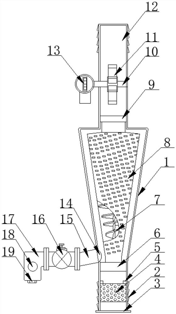
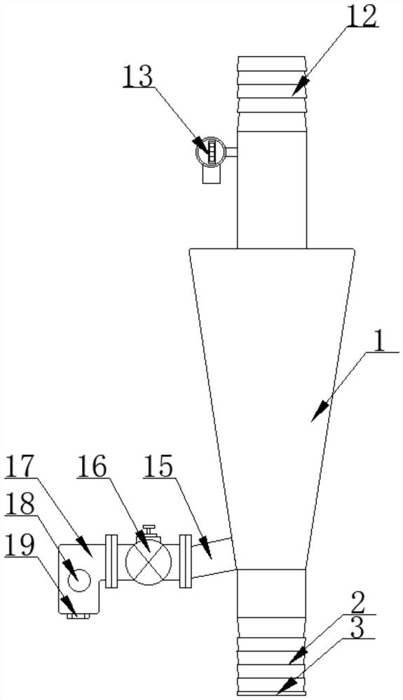
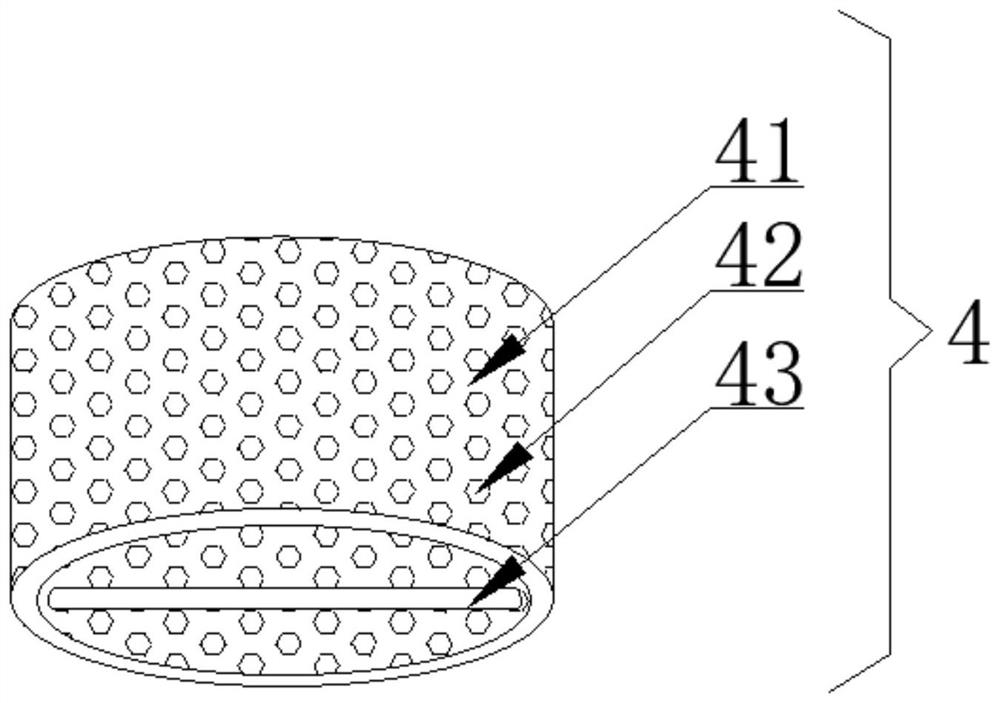
[0032] as attached figure 1 to attach Figure 6The shown filter device for hot washing fluid in oil production wells includes a conical outer cylinder body 1, the bottom end of the outer cylinder body 1 is fixedly equipped with an inlet-end upturning head 2, and the bottom end of the inlet-end upturning head 2 is fixedly installed There is a flange side 3 of the filter cartridge, a large-diameter filter cartridge 4 is clamped inside the inverted head 2 at th...


PUM

PropertyMeasurementUnit
lengthaaaaaaaaaa
widthaaaaaaaaaa

Abstract

The invention discloses a filtering device for hot washing liquid in oil production wells, and specifically relates to the field of well washing tools. A large-diameter filter cartridge and an inlet fixing seat are installed inside the inverted head at the inlet end, and a miscellaneous liquid separation cylinder is installed inside the inlet fixing seat and the outlet fixing seat. The side is equipped with a miscellaneous flange, a valve body, and a miscellaneous box. In the present invention, through the conical miscellaneous liquid separation cylinder and the conical helical blade, after the well washing fluid enters the washing liquid filter device, the conical miscellaneous liquid separation cylinder and the conical helical blade form an oblique direction along the tangential direction around the cylinder body. Centrifugal force, and the centrifugal force gradually increases along the outlet direction, so that the sand and gravel of various particle diameters in the well-washing fluid are thrown out of the miscellaneous liquid separation cylinder and separated from the well-washing fluid due to the huge centrifugal force, and the well-washing fluid mixed with small particles of formation sand can also be processed Better filtering effect.

Description

technical field [0001] The present invention relates to the technical field of well flushing tools, and more specifically, the present invention relates to a filter device for oil production well hot flushing liquid. Background technique [0002] Under the condition of high temperature and high pressure in the oil layer, the wax dissolves in the crude oil. After the crude oil flows into the wellbore, its pressure and temperature gradually decrease during the flow process from the bottom of the well to the wellhead. When the temperature and pressure drop to the wax precipitation point, the wax Precipitation from crude oil will cause wax deposition in the wellbore. When the wax deposition reaches a certain level, well cleaning and maintenance are required. Although the proportion of steam cleaning and self-circulation cleaning has been increased, conventional well cleaning is still the top priority. It is an essential work to ensure the normal production of oil wells. [0003...

Claims


Application Information

Patent Timeline
Patent Type & Authority Patents(China)
IPC IPC(8): B01D29/33B01D35/143
CPCB01D29/33B01D35/1435
Inventor 孙雨飞张艳杰杨雷戴海辉梁丽李石磊陈娜钟彬伟张海鹏李任庄立君李雪梅王立臣宋晶鑫刘翠霞刘洪俊
Owner 孙雨飞
Why Eureka
Try Eureka