Smart respirator and control method thereof

A technology of breathing control and respirator, which is applied in the direction of non-electric variable control, control/regulation system, and simultaneous control of multiple variables. It can solve the problems of circuit board short-circuit burning, internal component corrosion, etc., and achieve the effect of increasing gas exchange.

Active Publication Date: 2020-02-07
SHANGHAI FOUND AUTOMATIC EQUIP CO LTD
View PDF23 Cites 0 Cited by
  • Summary
  • Abstract
  • Description
  • Claims
  • Application Information

AI Technical Summary

Problems solved by technology

The long-term high humidity environment in the electric control box will cause corrosion of internal components; if condensed water is produced, it will cause short circuit and burnt circuit boards in the electric control box, and the consequences are very serious

Method used


Image

  • Smart respirator and control method thereof
  • Smart respirator and control method thereof
  • Smart respirator and control method thereof

Examples


Embodiment Construction

[0034] The present invention will be further described below in conjunction with the drawings.

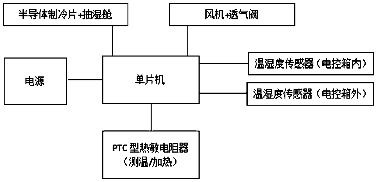
[0035] Such as figure 1 As shown, the smart respirator is mainly composed of a single-chip microcomputer control system (such as STM32F103ZET6), a temperature and humidity sensor placed outside the electric control box (such as Bosch BME280), a temperature and humidity sensor placed inside the electric control box (such as Bosch BME280), and PTC type Thermistor (temperature measurement / heating) (e.g. Heraeus M222 series), waterproof vent valve embedded with fan (e.g. Mingyixin Mexn1504), and semiconductor cooling sheet (e.g. Peltier TES1-07101) Composition of dehumidification chamber.

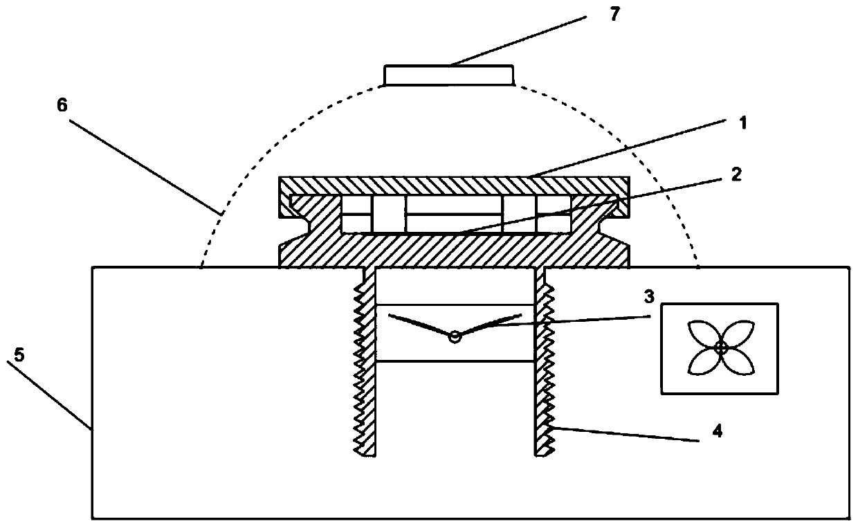
[0036] Such as figure 2 As shown, the product is mainly composed of the valve cover 1, the valve body 4, the waterproof and breathable membrane 2, the fan 3, the dehumidifying chamber 6, and the semiconductor refrigeration sheet 7. The breather valve is installed on the side wall of the electric contr...


PUM


Abstract

The invention discloses a smart respirator. The smart respirator is integrated with multiple functions such as waterproof, active ventilation, smart heating, smart refrigerating and monitoring of temperature and humidity. According to internal and external environment of an electric control box, if the smart respirator determines presence of "dewing" risk inside the electric control box, an instruction for running a blower, an instruction for heating PTC type thermistor or an instruction for refrigerating a semi-conductor cooler are respectively executed according to an actual situation, so asto perform good effects of "dehumidity" and "anti-dewing".

Description

Technical field [0001] The invention relates to an intelligent respirator and a control method thereof, which are applied to the field of new energy vehicles. Background technique [0002] With the progress of the times, people have higher and higher requirements for product reliability. As an emerging industry, new energy vehicles have more stringent requirements on the reliability of their internal components than the traditional automotive industry. At present, the waterproof and breathable valve used in the electric control box of new energy vehicles can balance the atmospheric pressure inside and outside the box, but the phenomenon of "condensation" in the box has not been effectively solved. "Condensation" mainly occurs in an environment with high humidity and a large temperature difference. The main reason for the "condensation" in the electronic control box is that the air with too high humidity accumulates in the box for a long time and is not discharged out of the box;...

Claims


Application Information

Patent Timeline
IPC IPC(8): G05D27/02
CPCG05D27/02
Inventor 朱华李过房吉淳
Owner SHANGHAI FOUND AUTOMATIC EQUIP CO LTD
Why Eureka
Try Eureka