
Drilling and perforating mechanism

A driving mechanism and drilling rod technology, applied in drilling equipment and methods, drilling equipment, directional drilling, etc., can solve the problem of low adjustability of drilling and drilling mechanisms, poor ability to adapt to different working conditions, and adjustment of drilling azimuth Inconvenience and other problems, to achieve the effect of good comprehensive use performance, improved adaptability, and good adjustability

Pending Publication Date: 2020-02-07
SHIJIAZHUANG COAL MINING MACHINERY
View PDF0 Cites 3 Cited by
  • Summary
  • Abstract
  • Description
  • Claims
  • Application Information

AI Technical Summary

Problems solved by technology

Due to the limited space in the underground roadway, the extension distance of the drilling and punching mechanism of a single slideway is very limited, and it is necessary to continuously lengthen the drill rod to achieve long-stroke drilling, and the work of lengthening the drill rod will cause the overall drilling low efficiency
In addition, the existing drilling and punching mechanism is usually a single drill bit, and the punching parts often need to be replaced in actual use
The overall adjustability of the drilling and drilling mechanism is low, and the adjustment of the drilling position of the drilling mechanism is inconvenient. It is necessary to frequently move the drilling equipment to carry out drilling operations at different positions and angles. The overall work efficiency is very low, and it is suitable for different working conditions. Poor ability

Method used


Image

  • Drilling and perforating mechanism
  • Drilling and perforating mechanism
  • Drilling and perforating mechanism

Examples


Embodiment Construction

[0026] Below in conjunction with accompanying drawing and specific embodiment the present invention is described in further detail:

[0027] The invention discloses a long drilling and punching mechanism, which can be used for drilling rods in coal mine roadways and tunnels in cooperation with equipment such as roadheaders. The following are specific examples:

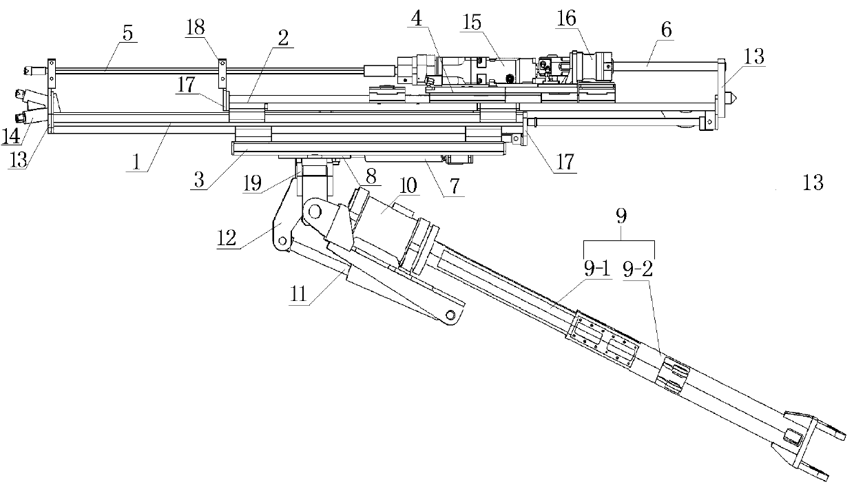
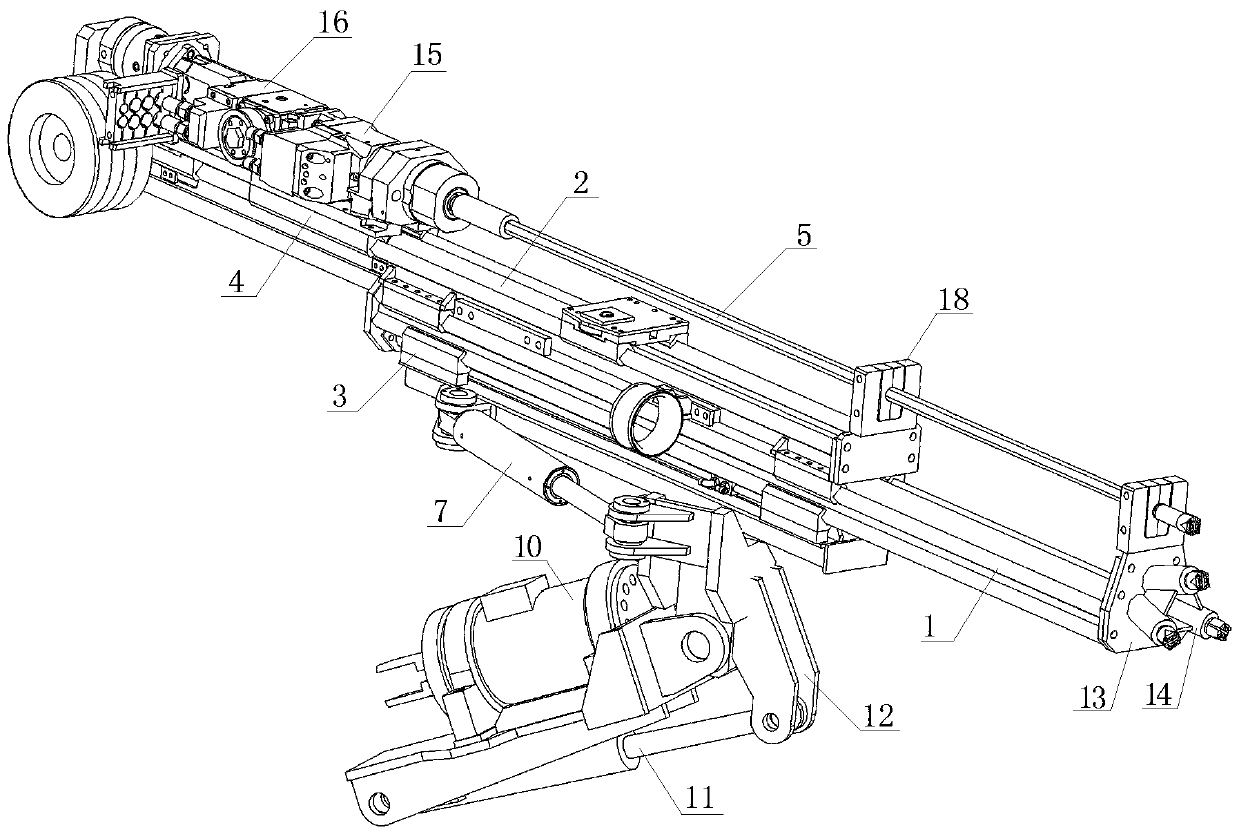
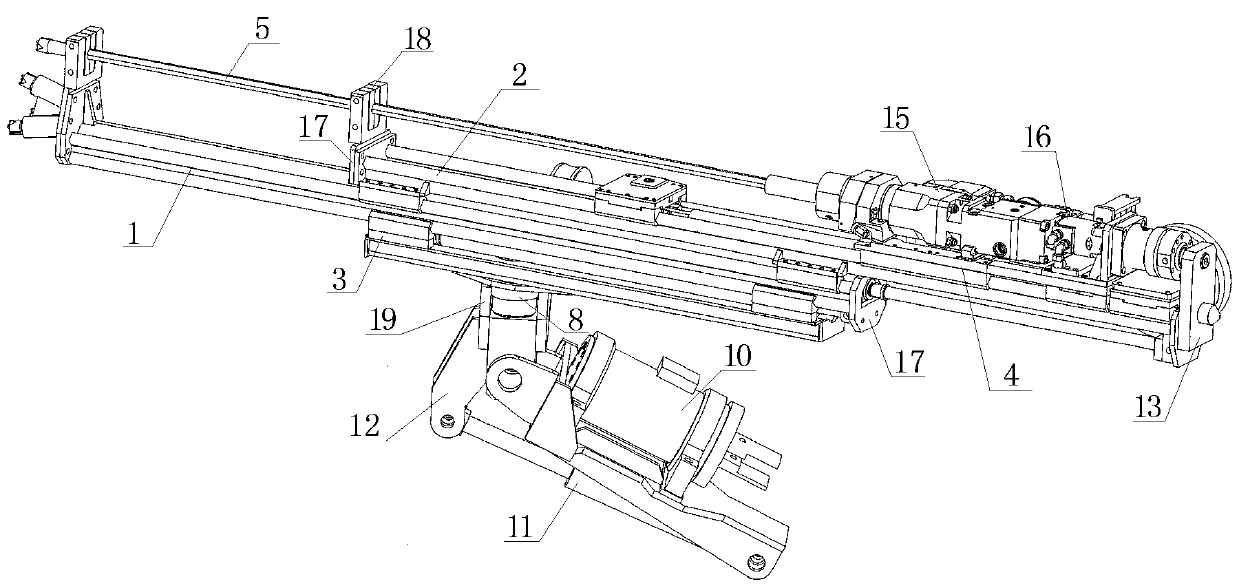
[0028] The invention relates to a drilling and punching mechanism, which realizes three-stage expansion and contraction by setting three slideways that can move relative to each other and two drill rods. On the premise that the required installation space remains unchanged, it is equivalent to lengthening the length of the slideway, thereby increasing the stroke of the drill pipe. Further, two drill rods can also be set on the drilling and punching mechanism, and different drill bits can be installed on the two drill rods to perform different types of drilling operations.

[0029] In order to achieve three-stage tele...


PUM


Abstract

The invention relates to a drilling and perforating mechanism and belongs to the technical field of drilling equipment. The drilling and perforating mechanism comprises a base, a first slideway sliding along the base, a second slideway sliding along the first slideway and a motor base sliding along the second slideway. Drill stems and driving mechanisms used for driving the drill stems to rotate are arranged on the motor base. The drilling and perforating mechanism further comprises positioning components used for performing positioning for perforating of the drill stems. According to the drilling and perforating mechanism provided by the invention, by arranging the two slideways and the motor base capable of sliding, long travel perforating in a narrow space is achieved; meanwhile, by arranging a rotating seat, a rotary motor and a supporting arm in a matched mode, perforating position adjusting in multiple directions and multiple angles can be achieved; and all the components of thedrilling and perforating mechanism provided by the invention are reasonable in arrangement and high in adjustability, the mechanism is particularly suitable for perforating in confined spaces such ascoal mine roadways and tunnels and has the good capability for adapting to different working conditions and good usability.

Description

technical field [0001] The invention relates to a drilling and punching mechanism, which belongs to the technical field of drilling equipment. Background technique [0002] The drilling and punching mechanism is mainly used for drilling underground roadways or tunnels, such as drilling long anchor cables and blast holes on the roadway walls. Due to the limited space in the underground roadway, the extension distance of the drilling and punching mechanism of a single slideway is very limited, and it is necessary to continuously lengthen the drill rod to achieve long-stroke drilling, and the work of lengthening the drill rod will cause the overall drilling low efficiency. In addition, the existing drilling and punching mechanism is usually a single drill bit, and the punching parts often need to be replaced in actual use. The overall adjustability of the drilling and drilling mechanism is low, and the adjustment of the drilling position of the drilling mechanism is inconveni...

Claims


Application Information

Patent Timeline
Patent Type & Authority Applications(China)
IPC IPC(8): E21B7/02E21B7/04E21B15/04
CPCE21B7/02E21B7/04E21B15/04
Inventor 刘伟李凤锦李树荣刘福新吴红林高春芳王宏奇邱彦海刘月广侯成志王志国
Owner SHIJIAZHUANG COAL MINING MACHINERY
Learn More