
Biological floccule filtering equipment applied to aquaculture

A biofloc, aquaculture technology, applied in sustainable biological treatment, biological water/sewage treatment, water aeration, etc., can solve the problems of large filling thickness of biochemical filter balls, large space of filter balls, difficult biochemical filter balls, etc. , to achieve the effect of speeding up the filtration and adsorption efficiency, expanding the contact area and improving the filtration effect

Inactive Publication Date: 2020-02-07
徐州健一家健康管理有限公司
View PDF1 Cites 6 Cited by
  • Summary
  • Abstract
  • Description
  • Claims
  • Application Information

AI Technical Summary

Problems solved by technology

[0004] The reference document adds a screen with a certain mesh number in the inner cylinder to improve the filtering effect, but there are still some defects: in the reference document, by filling the inner cavity of the filter inner cylinder with biochemical filter balls, aquatic product cultivation The water in the pool enters the filter inner cylinder through the water inlet pipe, and the water inlet pipe only has one water outlet. It is often difficult to fully contact the water body with the filled biochemical filter balls, that is, the biochemical filter balls located at the top and at the edge are difficult to be used. At the same time, the space loaded by the filter ball is relatively large, that is, the filling thickness of the biochemical filter ball is relatively large, and it is often not easy to quickly filter the water body, and the water body has a certain gravity, and it is difficult for it to spread rapidly around in the process of flowing downward. Larger, more affecting the filtration efficiency of water

Method used


Image

  • Biological floccule filtering equipment applied to aquaculture
  • Biological floccule filtering equipment applied to aquaculture
  • Biological floccule filtering equipment applied to aquaculture

Examples


Embodiment 1

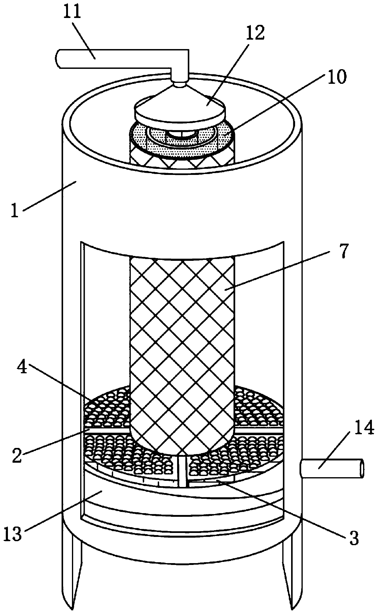
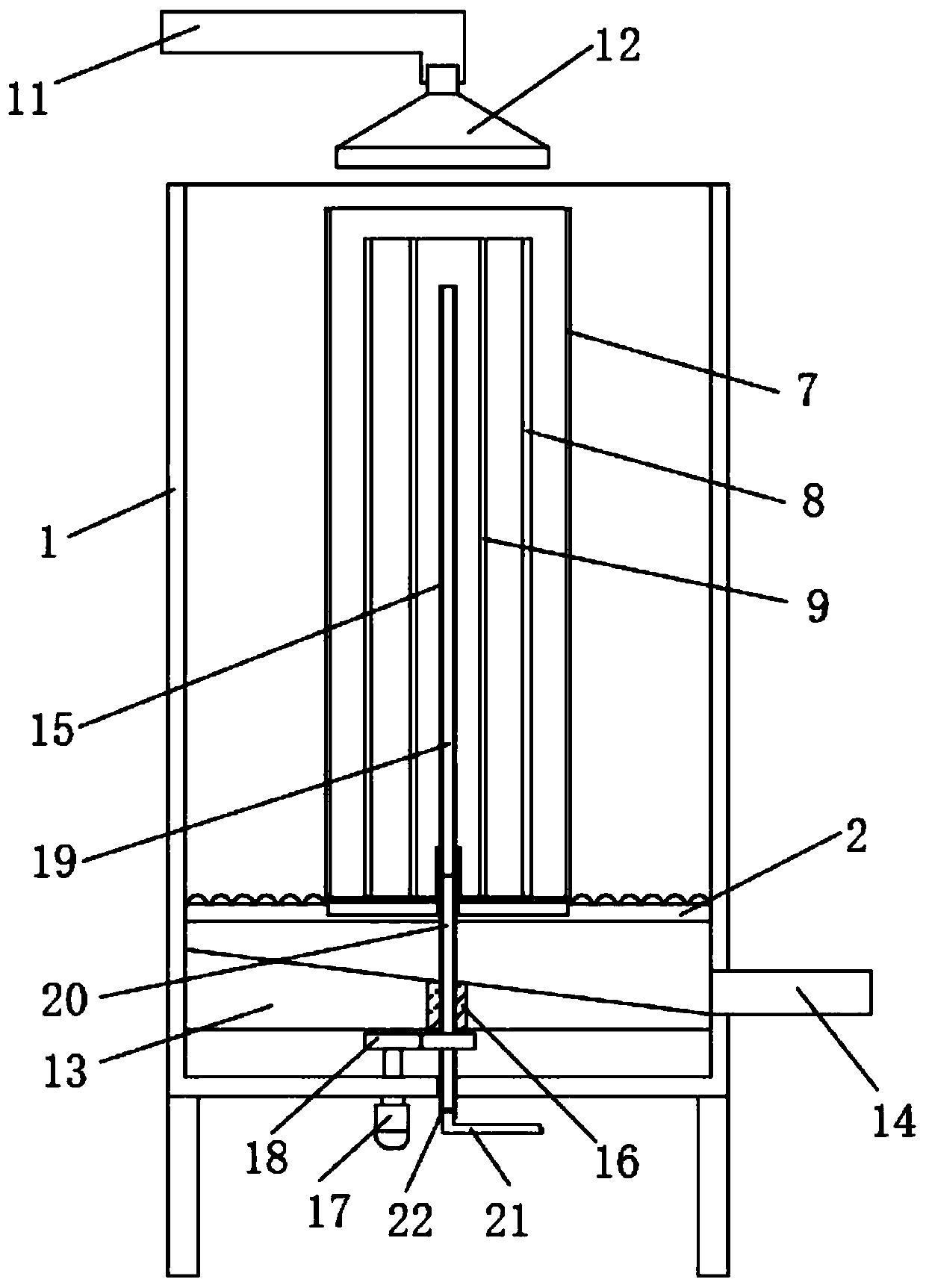
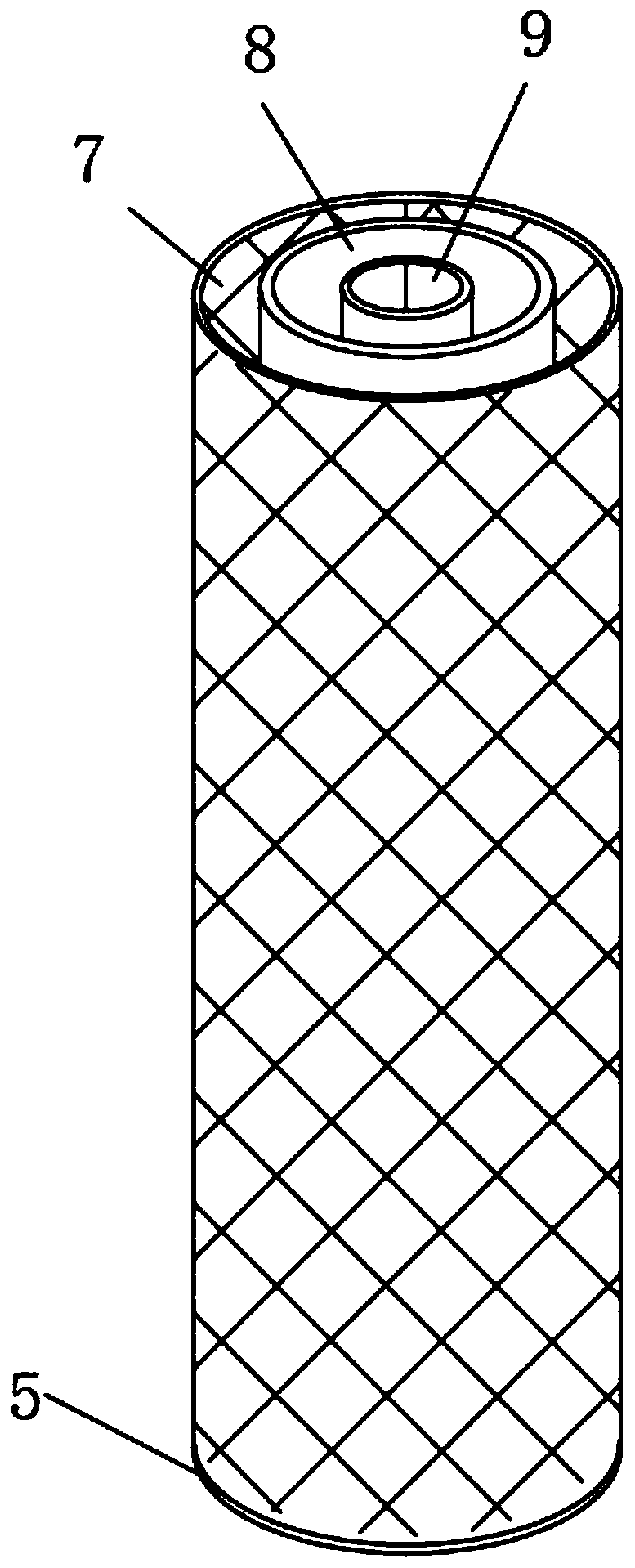
[0041] see Figure 1-4 , a biofloc filtering device applied to aquaculture, comprising an outer cylinder 1 and a cross-shaped support frame 2 fixedly installed near the bottom of the outer cylinder 1, a floc filling mechanism is fixedly embedded on the cross-shaped support frame 2, The side walls around the cross-shaped support frame 2 are fixedly embedded with a semi-arc filter screen 3, and the floc filling mechanism includes a circular filter bottom plate 5 embedded and connected to the top of the cross-shaped support frame 2. The circular filter bottom plate 5 The upper end of the upper end is fixedly connected with the outer ring frame 7, the middle ring frame 8 and the inner ring frame 9 from outside to inside in the direction of the center of the circle, between the outer ring frame 7 and the middle ring frame 8 and the middle ring frame 8 and the inner ring frame 9 Both are equipped with a filling layer, and the filling layer is filled with a biological floc layer 10. ...


PUM


Abstract

The invention discloses biological floccule filtering equipment applied to aquaculture, belongs to the technical field of biological filtration. According to the biological floccule filtering equipment applied to aquaculture, filled layers formed by a plurality of annular frames arranged inside and outside are filled with a biological floccule layer so as to play roles in supporting and limiting the biological floccule layer, when a water body flows through the biological floccule layer, the water body cannot shift due to excessive water flow impact force, meanwhile, a plurality of groups of nozzles corresponding to the positions of the filled layers are distributed inside and outside the bottom of a conical spray head, the water body fully diffuses onto the annularly distributed biological floccule layer, and the contact area of the biological floccule layer and the water body is effectively enlarged, so that the filtering effect is effectively improved, meanwhile, the water body is stirred through the cooperation of a rotating stirring pipe and an aeration pipe, namely, the filtering adsorption efficiency is effectively improved, meanwhile, the rapid and sufficient diffusion of gas in the aeration pipe is effectively realized under the rotating operation of the stirring pipe, and nutrients are supplied to the biological floccule layer.

Description

technical field [0001] The invention relates to the technical field of biological filtration, and more specifically relates to a biological floc filtering device applied to aquaculture. Background technique [0002] In the process of aquaculture, it is necessary to use a filter device to circulate and filter the aquaculture water. The filter using biofloc as the filter material is one of them. Biofloc refers to the organisms in the aquaculture water mainly composed of aerobic microorganisms. And inorganic bodies, the aggregates formed by bioflocs are generally formed by the mutual flocculation of bacteria, phytoplankton, mail debris and some inorganic substances, and the nutrient waste such as residual bait and feces in the breeding system can be degraded and converted into edible waste. Nutrients for the reproduction of planktonic algae to achieve the purpose of fertilizer and water in disguise. At present, the existing biofloc filters often fill the filter container with ...

Claims


Application Information

Patent Timeline
IPC IPC(8): C02F3/34C02F7/00C02F103/20
CPCC02F3/34C02F7/00C02F2103/20C02F2301/08Y02W10/10
Inventor 潘静波宋丽
Owner 徐州健一家健康管理有限公司
Learn More