Drainage pipe connector with gas purification function for underground engineering construction

A technology for gas purification and underground engineering, applied in the field of underground engineering, can solve problems such as air pollution, and achieve the effect of improving purification effect, reducing space occupation and improving work efficiency

Active Publication Date: 2020-02-07
聊城市洛溪信息科技有限公司
View PDF7 Cites 2 Cited by
  • Summary
  • Abstract
  • Description
  • Claims
  • Application Information

AI Technical Summary

Problems solved by technology

[0005] The purpose of the present invention is to provide an energy-saving, environment-friendly, space-saving drainage pipe joint with gas purification function for underground engineering construction to solve the problem of serious air pollution at the existing underground engineering construction site

Method used


Image

  • Drainage pipe connector with gas purification function for underground engineering construction
  • Drainage pipe connector with gas purification function for underground engineering construction
  • Drainage pipe connector with gas purification function for underground engineering construction

Examples


Embodiment 1

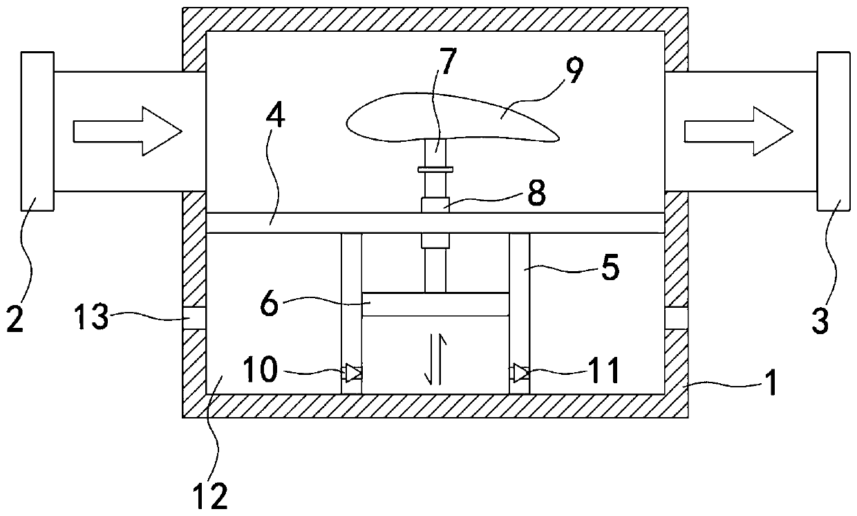
[0023] Such as Figure 1-2 As shown, a drainage pipe joint with gas purification function for underground engineering construction includes a purification box 1, the two ends of the purification box 1 are respectively connected with a water inlet pipe 2 and a drainage pipe 3, and the interior of the purification box 1 is sealed and connected with a horizontally arranged Partition 4, the underside of the partition 4 is provided with a pumping part 5, the pumping part 5 is slidingly and sealed connected with a pumping plate 6, the upper end of the pumping plate 6 is fixedly connected with a connecting rod 7, and the parting plate 4 is penetrated and fixed A casing 8 is connected.

[0024] The upper end of the connecting rod 7 runs through the casing 8 and is fixedly connected with the wing flow plate 9. The upstream surface of the wing flow plate 9 is set facing the water inlet pipe 2. When the water flow flows from the water inlet pipe 2 to the drain pipe 3, it will directly ac...

Embodiment 2

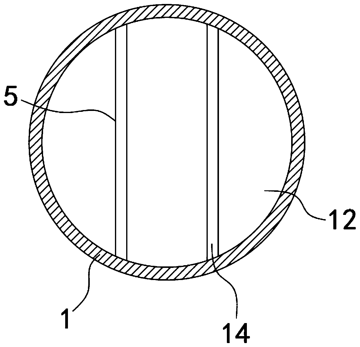
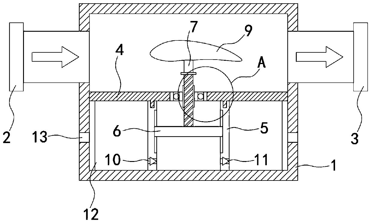
[0029] Such as Figure 3-5 As shown, the difference between this embodiment and Embodiment 1 is that the pumping part 5 includes a pumping cylinder 15, the lower end of the pumping cylinder 15 is fixedly connected with the inner side wall of the purification box 1, and the upper end of the pumping cylinder 15 rotates with the partition plate 4 Connection, specifically, the lower end of the dividing plate 4 is provided with an annular protrusion 19, and the upper end of the pump cylinder 15 is provided with an annular chute, the annular protrusion 19 is located in the annular chute and is connected with the annular chute for sealing and rotation, the pump air cylinder 15, The clapboard 4 and the purification box 1 together form a closed space. The lower end of the clapboard 4 is fixedly connected with a commutator cover 16, and the commutator cover 16 is provided with a diversion hole 17 correspondingly. Rotational connection, the casing 8 is provided with an internal thread, a...


PUM


Abstract

The invention belongs to the field of underground engineering and in particular relates to a drainage pipe connector with a gas purification function for underground engineering construction. The drainage pipe connector comprises a purification tank, wherein a water inlet pipe and a drainage pipe are respectively connected with both ends of the purification tank; a partition plate which is horizontally arranged is connected inside the purification tank in a sealed manner; a gas pump part is arranged on the lower side of the partition plate; a gas pump plate is connected inside the gas pump part in a sliding sealed manner; a connecting rod is fixedly connected with the upper end of the gas pump plate; a casing is fixedly connected with the partition plate in a penetration manner; the upperend of the connecting rod penetrates through the casing and is fixedly connected with a wing plate; the incident flow surface of the wing plate is arranged right aligned to the water inlet pipe; a one-way gas inlet and a one-way gas outlet are formed in the side wall of the gas pump part; and a purification cavity is formed between the gas pump part and the inner side wall of the purification tank. Due to arrangement of the wing plate, the wing plate can be driven to move up and down through variation of flowing speeds of water flows of a sewage pipe, so that an extra driving part does not need to be arranged, not only are energy conservation and environment protection better achieved, but also emission of heat can be reduced, and the arrangement difficulty of a gas purification device canbe also greatly reduced.

Description

technical field [0001] The invention belongs to the field of underground engineering, in particular to a drainage pipe joint with gas purification function for underground engineering construction. Background technique [0002] During the construction of underground projects, due to the long and narrow space of the construction site, diesel engines and other equipment will produce more exhaust gas when they are working, and the exhaust gas emitted by diesel engines usually contains a large number of large particles of smoke particles, which makes the air dust content of underground engineering construction sites Higher, poor air quality, endangering the health of construction workers. [0003] Due to the lack of space on the construction site of the underground project, the additional gas purification device will not only take up more space, but also cause inconveniences such as wiring, replacement, and maintenance. In addition, the existing gas purification device usually i...

Claims


Application Information

Patent Timeline
Patent Type & Authority Applications(China)
IPC IPC(8): B01D49/00
CPCB01D49/00
Inventor 翁连清
Owner 聊城市洛溪信息科技有限公司
Why Eureka
Try Eureka