Stainless steel fan with gas purification function

A gas purification and stainless steel technology, which is applied to liquid fuel engines, parts of pumping devices for elastic fluids, mechanical equipment, etc., can solve the problems of inconvenient installation and maintenance, inconvenient installation, and inability to purify gas, etc., and achieve improvement Working environment, easy installation and disassembly, and convenient storage effect

Active Publication Date: 2021-01-08
JIANGSU HENGKANG ELECTRICAL
View PDF8 Cites 3 Cited by
  • Summary
  • Abstract
  • Description
  • Claims
  • Application Information

AI Technical Summary

Problems solved by technology

[0003] The existing fan has the disadvantage of inconvenient installation during operation, which brings inconvenience to the early installation and later maintenance, and cannot purify the gas, which endangers personal health and working environment, and is also inconvenient to store and prevent dust.

Method used


Image

  • Stainless steel fan with gas purification function
  • Stainless steel fan with gas purification function
  • Stainless steel fan with gas purification function

Examples


Embodiment 1

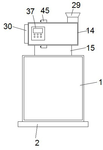
[0033]SeeFigure 1-9According to an embodiment of the present invention, a stainless steel fan with gas purification function includes a receiving cavity 1, a mounting seat 2 is fixed at the bottom of the receiving cavity 1, and a screw 3 and Screw two 4, the threads on the screw one 3 and the screw two 4 are reverse threads, the screw one 3 and the screw two 4 are connected by a coupling 5, and the screw one 3 is far away One end of the coupling 5 is connected to the output end of the motor 6, the motor 6 is fixedly installed on the inner wall of the receiving cavity 1, and the end of the screw rod 4 away from the coupling 5 penetrates through the bearing One 7 extends into the bearing one 7, the outer sides of the screw one 3 and the two screw 4 are threadedly connected with a sliding block 8, and the surface of the sliding block 8 is fixed with a movable shaft, the movable shaft One is sleeved with a support frame 9, one end of the support frame 9 away from the movable shaft is sl...

Embodiment 2

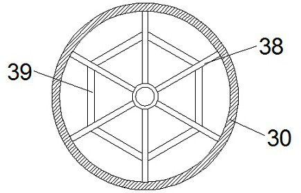
[0036]SeeFigure 1-9For the air inlet 30, a dust filter plate 38 is installed at the air inlet 30, and reinforcing ribs 39 are fixed between the dust filter plates 38. For the control box 37, a display screen and an operation button are installed on the control box 37, and the display screen is electrically connected to the operation button.

[0037]Through the above-mentioned solution of the present invention, the beneficial effect is: by providing the dust filter plate 38, the foreign matter with large particles can be blocked from the air inlet 30, and the stainless steel fan can be protected; the display screen and the operation button are convenient Manual adjustment control.

Embodiment 3

[0039]SeeFigure 1-9For the filter cartridge 31, a first filter screen layer 40, a second filter screen layer 41 and an activated carbon adsorption layer 42 are fixedly installed inside the filter cartridge 31 in sequence.

[0040]Through the above-mentioned solution of the present invention, the beneficial effect is that by providing the first filter mesh layer 40, the second filter mesh layer 41 and the activated carbon adsorption layer 42 for layer-by-layer filtration and adsorption, the filtration effect is improved.


PUM


Abstract

The invention discloses a stainless steel fan with a gas purification function. The stainless steel fan comprises a storage cavity, wherein a mounting base is fixedly arranged at the bottom of the storage cavity, a first screw and a second screw are arranged in the storage cavity, threads on the first screw and the second screw are reverse threads, and the first screw and the second screw are connected through a coupler; the end, away from the coupler, of the first screw is connected with the output end of a first motor, the first motor is fixedly installed on the inner wall of the storage cavity, the end, away from the coupler, of the second screw penetrates through a first bearing and extends into the first bearing, sliding blocks are in threaded connection with the outer sides of the first screw and the second screw, and first movable shafts are fixedly arranged on the surfaces of the sliding blocks; and the first movable shafts are sleeved with supporting frames, the ends, away from the first movable shafts, of the supporting frames sleeve second movable shafts, the second movable shafts are fixed to a connecting block, the top of the connecting block is fixedly connected witha lifting plate, and a fixing base is fixedly arranged at the top of the lifting plate. The stainless steel fan has the beneficial effects that the working environment is greatly improved, and the health of workers is protected.

Description

Technical field[0001]The invention relates to a stainless steel fan, in particular to a stainless steel fan with gas purification function.Background technique[0002]A fan is a machine used to compress and transport gas. It can supply gas by converting rotating mechanical energy into pressure energy and kinetic energy. The existing fan usually has two pipes, one of which is the air inlet pipe. It is used to draw the air in the environment into the fan, compress it, and then send it out through the air outlet pipe to achieve the effect of the fan.[0003]Existing fans have the disadvantage of inconvenient installation during the operation process, which brings inconvenience to the early installation and later maintenance, and can not purify the gas, endangers personal health and working environment, and is not convenient to store and prevent dust .[0004]For the problems in related technologies, no effective solutions have yet been proposed.Summary of the invention[0005]The purpose of th...

Claims


Application Information

Patent Timeline
Patent Type & Authority Applications(China)
IPC IPC(8): F04D25/08F04D29/00F04D29/60F04D29/70
CPCF04D25/08F04D29/002F04D29/601F04D29/701
Inventor 王正方刘万勤董传友刘正东刘迪群张为军孙勇安
Owner JIANGSU HENGKANG ELECTRICAL
Why Eureka
Try Eureka