Method and system for detecting laser damage based on optical element
A technology for optical components and laser damage, which is applied in the field of optical measurement and can solve problems such as low detection accuracy and detection errors
- Summary
- Abstract
- Description
- Claims
- Application Information
AI Technical Summary
Problems solved by technology
Method used
Image

Examples
Embodiment 1
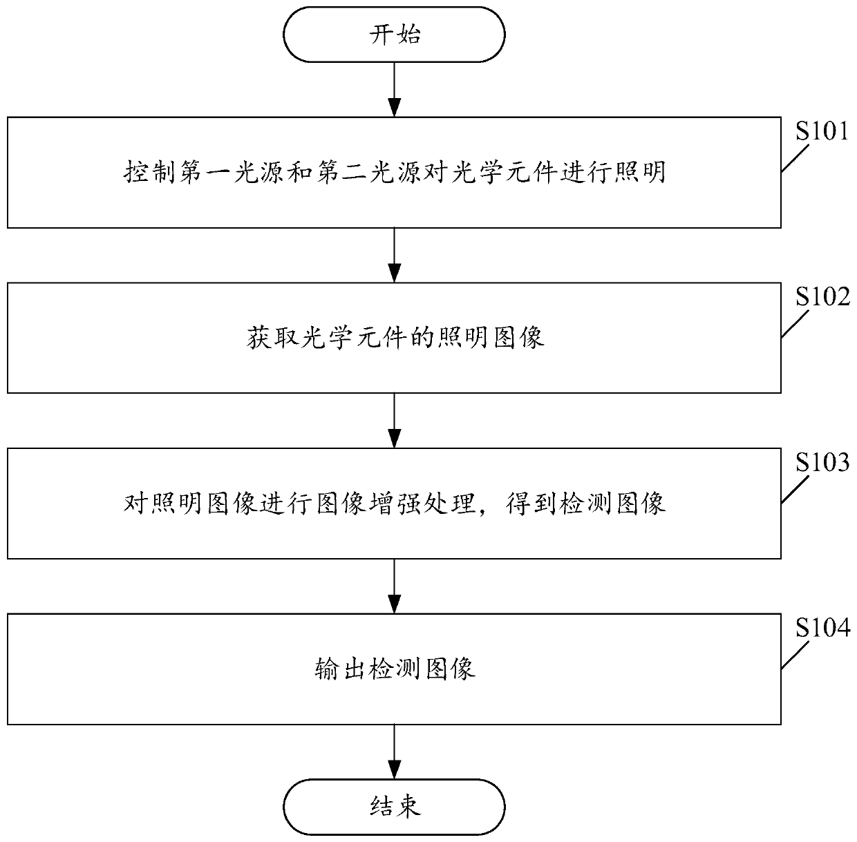
[0046] Please see figure 1 , figure 1 A schematic flowchart of a laser damage detection method based on an optical element is provided for an embodiment of the present application. This method is applied to the scene of laser damage detection of optical components, and can be specifically applied to scenes such as laboratories. Among them, the laser damage detection method based on optical components includes:
[0047] S101. Control the first light source and the second light source to illuminate the optical element.
[0048]In this embodiment, the first light source may be a bright field light source, and the second light source may be a dark field light source.
[0049] In this embodiment, the first light source is an incoherent light source, and the second light source is a collimated laser source.
[0050] In this embodiment, the first light source and the second light source can move the optical element during the process of illuminating the optical element, wherein t...
Embodiment 2
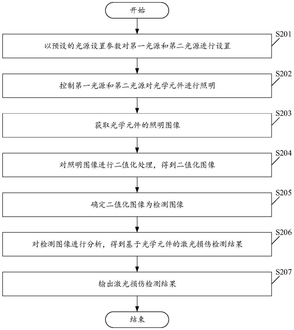
[0069] Please see figure 2 , figure 2 It is a schematic flowchart of another optical element-based laser damage detection method provided in the embodiment of the present application. figure 2 The schematic flowchart of the described optical element-based laser damage detection method is based on figure 1 The schematic flow chart of the described optical element-based laser damage detection method is improved. Among them, the laser damage detection method based on optical components includes:
[0070] S201. Set the first light source and the second light source with preset light source setting parameters.
[0071] In this embodiment, light intensity, light irradiation position, light source visit position, etc. can all be determined as light source setting parameters.
[0072] In this embodiment, in order to increase the scattered light intensity of the laser damage point and improve the detection accuracy, the laser is illuminated forwardly, and the angle A between the...
Embodiment 3
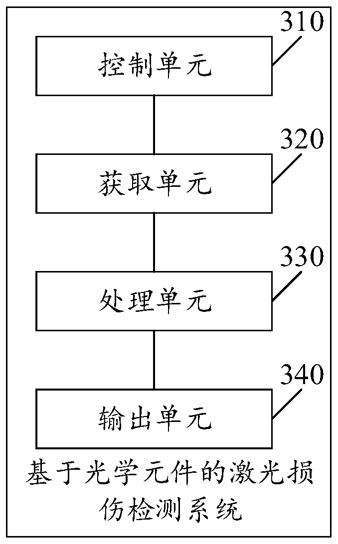
[0096] Please see image 3 , image 3 A schematic structural diagram of a laser damage detection system based on an optical element provided in an embodiment of the present application. Among them, the laser damage detection system based on optical components includes:
[0097] The control unit 310 is configured to control the first light source and the second light source to illuminate the optical element.
[0098] The acquiring unit 320 is configured to acquire an illumination image of the optical element.
[0099] The processing unit 330 is configured to perform image enhancement processing on the illumination image to obtain a detection image.
[0100] The output unit 340 is configured to output the detection image.
[0101] In this embodiment, the optical element-based laser damage detection system may refer to any explanations described in Embodiment 1 or Embodiment 2, which is not limited in this embodiment.
[0102] Visible, implemented image 3 The described opt...
PUM
 Abstract
Description
Claims
Application Information
 - R&D
- Intellectual Property
- Life Sciences
- Materials
- Tech Scout
- Unparalleled Data Quality
- Higher Quality Content
- 60% Fewer Hallucinations
Browse by: Latest US Patents, China's latest patents, Technical Efficacy Thesaurus, Application Domain, Technology Topic, Popular Technical Reports.
© 2025 PatSnap. All rights reserved.Legal|Privacy policy|Modern Slavery Act Transparency Statement|Sitemap|About US| Contact US: help@patsnap.com